This thread has been locked.

If you have a related question, please click the "Ask a related question" button in the top right corner. The newly created question will be automatically linked to this question.

TPS54360: Problem with Heavy Load using TPS54360 Reference Design

Part Number: TPS54360

Hello TI team,

I am Trong, our Hardware Team got a problem with Power Supply using TPS54360 Reference Design.

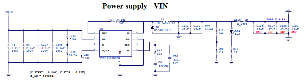
We designed more than 10 PCBs using the same Power Supply Circuit as above. Some of them work well while others do not.

Phenomenon: There are strong oscillations when Heavy Load starts to be connected (below picture), which affect all circuits using +5V power line.

After testing, I figured out this problem caused by SW pin and COMP pin of TPS54360.

1. Testing with PCB that has TPS54360 work well:

Channel 1 (Yellow): Voltage Clamp at COMP pin.

Channel 2 (Pink): Switching waveform at SW pin.

  • Light Load:

  • Heavy Load:

2. Testing with PCB that has problem with TPS54360:

Channel 1 (Yellow): Voltage Clamp at COMP pin.

Channel 2 (Pink): Switching waveform at SW pin.

There is no change at COMP Voltage and SW waveform when I turn on the Heavy Load. I guess that TPS54360 is kept at Pulse Skipping Eco-mode.

I tried to remove TPS54360 and re-solder a brand new part TPS54360, changed C88 from 33pF to 39pF (exactly as Reference Design), but I still received the same issue.

Please kindly help me troubleshoot this issue.

  • Hi Trong,

    You might check the load transient response when the converter is operating in CCM (i.e. a higher load for the light-load level).

    Regards,

    Tim

  • Hi Timothy,

    Thank you very much for your quickly reply.

    After reading carefully TPS54360's datasheet, I recognize that TPS54360 has Current Sense and controls Peak Switch Current.

    As I mentioned on my first post, I think my issue caused by TPS54360 can not escape from Pulse Skip Eco-mode. (Using Oscilloscope when connecting Heavy Load, I detected this reason)

    Then, I decided to change the Inductor on my Power Error PCB to a new part and this issue was solved. Now all of my Power Error PCBs work normally as I do just one change: Replace the Inductor from Part:DR1050-8R2-R to Part:7447797820 (a brand new Part:DR1050-8R2-R also fixed the issue)

    Could you please show me the reason why some parts (DR1050-8R2-R) caused this power error?

  • Hi Trong,

    Yes, the TPS54360 has a peak current-mode control architecture (with the usual transconductance error amplifier, slope compensation and PWM comparator).

    Note that the saturation current of the Eaton inductor is somewhat low (5A). In general, the sat current of the inductor should be higher than the peak current limit threshold of the converter, in this case 5.5A typ, 6.8A max (see datasheet, page 7). Recommendation is to choose an inductor with sat current > 7A.

    Regards,

    Tim

  • Your explanation is very helpful for me.

    My problem was solved and we can close this topic now.

    Thank you very much, Mr. Timothy.