This thread has been locked.

If you have a related question, please click the "Ask a related question" button in the top right corner. The newly created question will be automatically linked to this question.

BQ24725A: Excessive volts on Vcc when switching on the adapter with no battery fitted

Part Number: BQ24725A

We are developing a charger for a Li-Ion battery with the requirements:

Max charge voltage 16.8V

Max Charge Current 700mA

Min Bat volts 10.0V

Adapter Voltage 20V

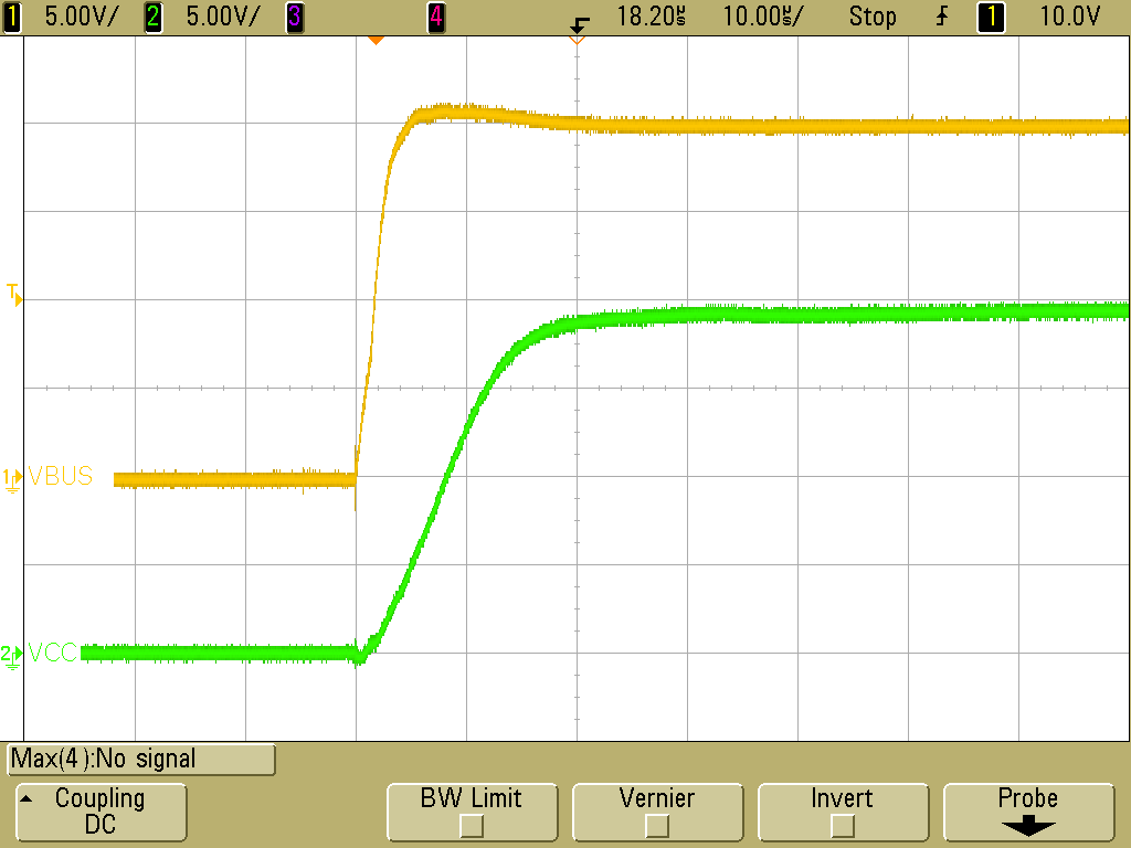
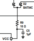
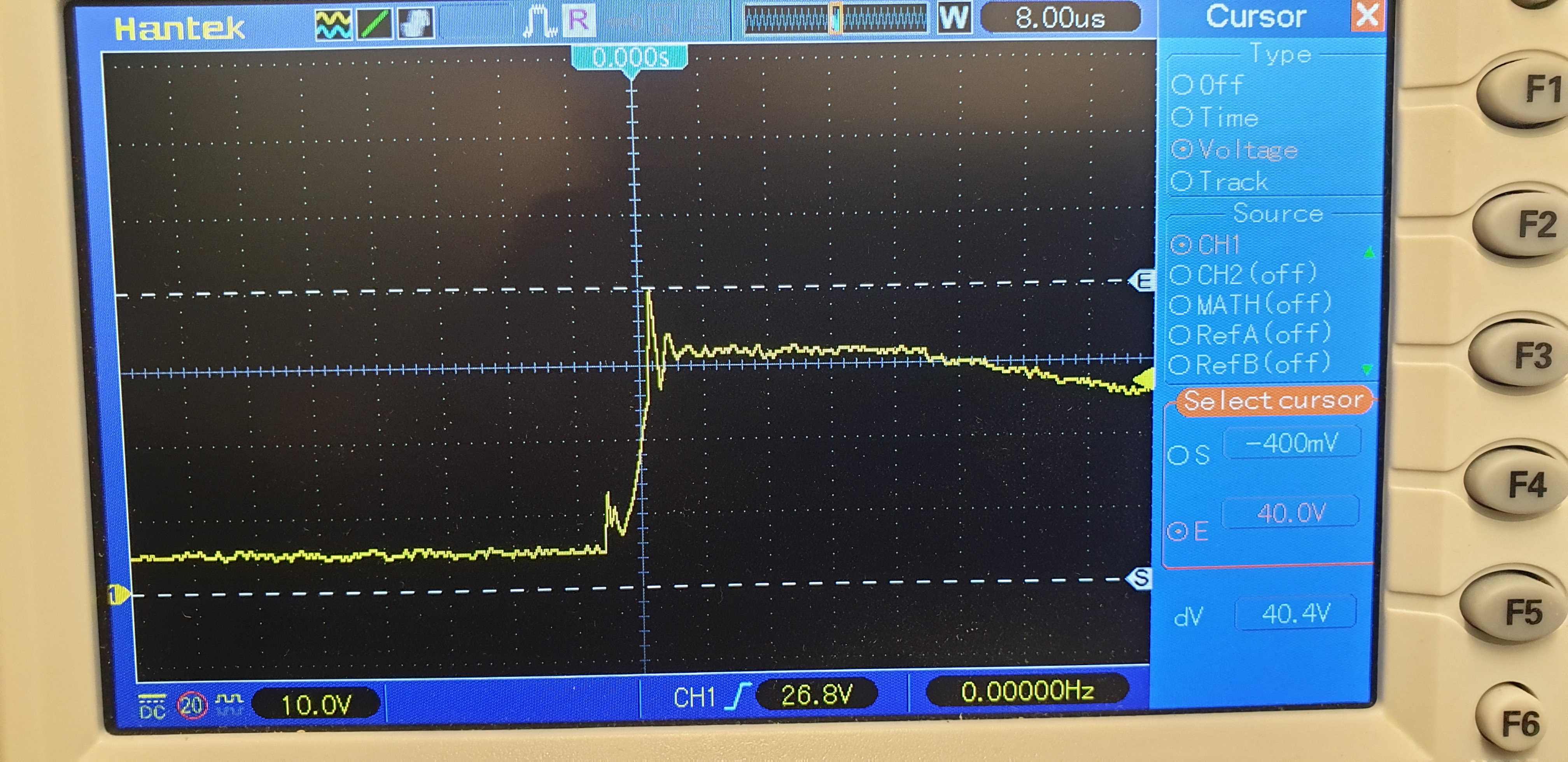
Without a battery connected on connecting the adapter we observe up to 40V on the Vcc pin of the bq24725A.

I have tried adding a 2R and 2.2uF at the DC in witch helped reduce the ringing a little (5V perhaps).

I believe this is damaging the regulators uC as well as the charger chip such that when a battery is plugged in all four fets in the power path fail spectacularly.

However if the battery is plugged in first followed by the adapter the charger seems to work without smoke.

Should we be able to power the BQ24725A from the adapter without the battery connected?

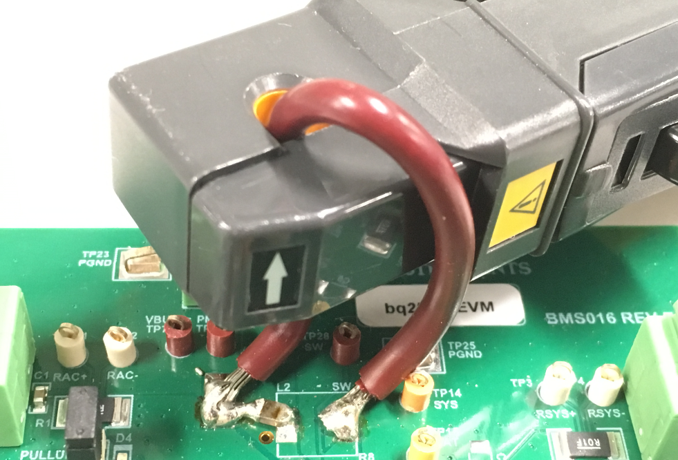
This is our first off circuit, please note that Z5 or Vsys does not connect to anything. 


Please could you advise as to how to prevent these 40V overshoots when plugging in the adapter without a battery.

Thanks

MG

  • Hi Martin,

    Yes, you should be able to power the BQ24725A from the adapter with no battery connected.

    I tested this on a BQ24725A EVM and did not see an overshoot on VCC. I set VBUS (DC_IN in your schematic) to 20 V and had no battery connected, but VCC did not overshoot when I plugged in VBUS, as shown below.

    I see a few issues with your schematic that could be related to your VCC overshoot. Please remove C29 and make sure that C28 is connected the same way that we show in our typical application diagram.

    Are you using a power supply or a real adapter? Do you have a different power supply/adapter that you can try? Also, can you please capture a waveform that shows VBUS and VCC when you plug in the adapter, similar to my waveform above?

    Best regards,

    Angelo

  • Hell Angelo,

    I removed C29 and moved C28 as you suggested and now get DC_IN and VCC waveforms very similar to yours.

    Do you think the inductor L2 value 5.6uH is suitable for 700mA charge current? Perhaps the ripple will be too high?

    Thanks,

    Martin

  • Hi Martin,

    Glad to hear that the 40 V overshoot issue was resolved!

    A 5.6 µH inductor will be able to provide a 700 mA charge current. However, depending on your operating conditions, the ripple current may be high enough that the converter will operate in DCM instead of CCM (please see Section 8.4.11 in the datasheet for more details). A duty cycle close to 0.5 and a lower switching frequency will also increase the ripple current, as shown in the following equation:

    Can you give me more information about your application and let me know your battery's capacity? A 700 mA max charge current seems low for a 4s battery application.

    Best regards,

    Angelo

  • Hello Angelo,

    We are developing an intelligent modular 248Ah rechargeable battery system made up of up to 36 off 6900mAh batteries.

    Each battery has a pcb which has the charger chip and a micro for communications.

    We have restricted the charge current to 700mA to try to minimize the heat (x36 in the same box).

    We need to be able to hot plug the adapter and the battery.

    I have removed C29 and re positioned C28 as you recommended.

    Also added 2R and 2.2uF to ground on adapter input (DC_IN).

    Would you recommend 2R and 2.2uF to ground on the battery connector?

    I am questioning the L and C choice, would 22uH or even 47uH be better regarding ripple?

    Would it be possible for you to review our schematic?

    Many thanks for your help,

    Martin

  • Hi Martin,

    Here are my comments regarding your schematic (after implementing the changes you described):

    1) Please increase C40 (the REGN cap) from 100 nF to 1 µF

    2) Please make sure your SRP and SRN network matches the typical application diagram:

    3) R19 (bottom resistor of the ILIM resistor divider) is marked as DNF. What is the intended value here?

    4) There is no BATFET in your schematic. Will you have a system connected at Z5, or are you using the BQ24725A solely to charge the battery?

    Regarding the 2 Ω resistor and 2.2 µF capacitor connected from BAT to GND: These components are used for voltage spike damping. They are usually more important on the adapter side and less important on the battery side, but you can add these components in if you wish.

    Regarding the L and C selection: A larger L would reduce the ripple current, but the inductor would also be physically larger. If space is a constraint in your application, then it may be better to use a more moderate L. Typically, the ripple current is designed to be 20%-40% of the max charge current (please see Section 9.2.2.4 in the datasheet for more details on inductor selection). 22 µH could be a suitable value, but again, this also depends on your operating conditions, such as switching frequency, input voltage, and output voltage.

    Best regards,

    Angelo

  • Hello Angelo,

    Thanks for you previous reply, we have already implemented 1),2) and 3) on our prototype.

    4) We are using the BQ24725A solely as a battery charger.

    We have also purchased an eval board BQ24725AEVM-710.

    We are struggling with the ripple calculations and L selection, our calculations based on the eval board are below:

    Adapter input voltage of 24V.

    Lowest allowed battery volts 10V.

    Max Charge current of 704mA.

    Battery charge voltage 16.8V.

    The Eval board has a 4.7uH L fitted.

    Data Sheet Page 30 equation (5) states Iripple = (Vin * D * (1-D))/(fs * L)

    D = 10/24 = 0.41

    fs is default 750KHz

    Iripple  = (24 * 0.41 * 0.59)/(750000 * 0.0000047) = 1.65A

    A ripple current of 1.65A on a max charge current of 0.704A seems wrong, you suggest 20% to 40% of the max charge current (0.21A).

    What are the repercussions of such a large ripple current in a design? Why the 20% to 40% of max charge current?

    However your eval board seems to charges a battery OK with these values.

    The average charge current measured using a DVM was just over 600mA.

    How do you suggest we measure the ripple current ?

    It is too noisy to use a scope with differential input across the sense resistor.

    I would like to change the L to 22uH but would like to be able to measure an improvement in the current ripple.

    What value of L do you recommend for our application?

    Best regards,

    Martin


  • Hi Martin,

    The "20% to 40%" guideline is not a hard and fast rule, but it usually provides a good tradeoff between inductor size and efficiency.

    When designing a buck converter, we generally want a stable output voltage with very low ripple. On the other hand, minimizing the inductor current ripple is much less of a concern. Since we have some leeway with the inductor current ripple and do not need to minimize it as much as possible, this allows the use of smaller inductors, which saves both space and cost.

    On the flip side, if we allowed an excessively high ripple current, then this may cause the converter to operate in DCM instead of CCM, especially in light load conditions. DCM operation tends to be less efficient than CCM operation. Therefore, the "20% to 40%" guideline is a suitable middle ground for most applications because it allows us to use smaller inductors while still operating in CCM most of the time.

    Regarding how to measure the inductor current ripple, we typically do this by de-soldering the inductor and removing it from the EVM. We then solder one end of the inductor to a wire such that the wire and the inductor are in series. Finally, we solder the wire/inductor back onto the EVM. The reason for adding in a wire is so we can use a current probe to see the inductor current waveforms on an oscilloscope. The picture below is not a BQ24725A EVM, but hopefully it still gives you an idea of the type of connection I'm describing:

    A 22 µH inductor seems suitable for your application.

    Best regards,

    Angelo