


HI TI
I layout to schematic datascheet
The problem is that when the load is used, the voltage drops. Imax < 20mA
You give me prize pphaps to overcome. Thanks !
Original question:

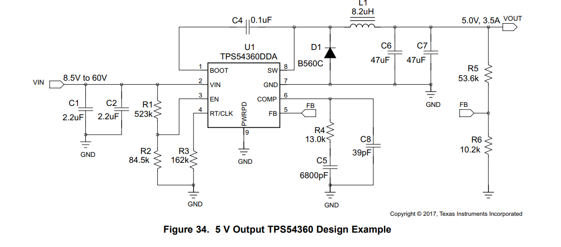
TPS54360: Problem with Heavy Load using TPS54360 Reference Design
HI TI
I layout to schematic datascheet
The problem is that when the load is used, the voltage drops. Imax < 20mA
You give me prize pphaps to overcome. Thanks !


