This thread has been locked.

If you have a related question, please click the "Ask a related question" button in the top right corner. The newly created question will be automatically linked to this question.

How to measure leakage inductance considering short circuit wire inductance

Other Parts Discussed in Thread: TEST2, SFRA

Hi everbody,

I'm designing an RCD clamp snubber circuit for a flyback converter to absorb the current in the leakage inductance when the drain voltage exceeds the clamp capacitor voltage. Finally, this will prevent switch overvoltage. 

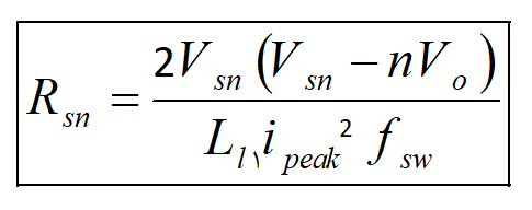
OK, the most important matter is to measure the leakage in order to be able to calculate the snubber resistor value from the equation below.

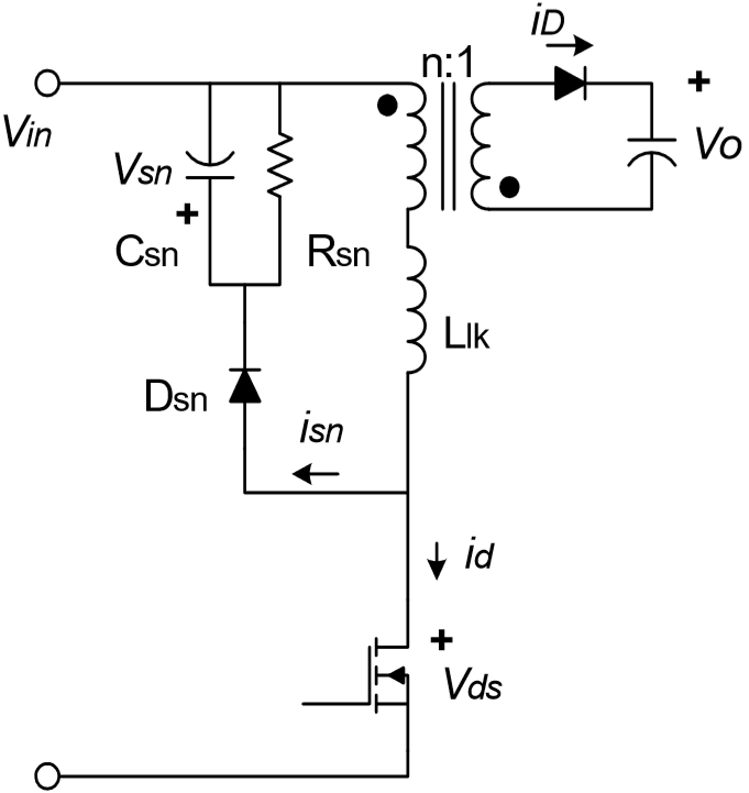
schematic of the converter+snubber circuit

and the waveforms are shown below

There are different techniques to find and measure the leakage inductance. One is to use two-stage measurement:

  1. Open circuit test (the secondary winding is open circuit, and the LRC meter measures the {primary inductance (Lp)+primary leakage inductance(L1l)} )
  2. Shorted-circuit test (the secondary winding is shorted, so the LRC meter only measures  the primary leakage inductance (L1l) 

But, the technical problem is that the wire we use to short circuit the secondary winding has its own impedance (resistance+inductance). Therefore the inductance which is measured in test2 (short circuit test) consists of the primary leakage inductance+N^2*short circuit wire's inductance. For more details, please take a look at this link.

Considering this issue (the wire used to short circuit the secondary winding is not ideal and has inductance which affects on the value of inductance measured in the short circuit test as mentioned above), does anybody have any practical technique to measure the primary leakage inductance?

I myself want to use a frequency response analyzer to solve this issue. Because I think the inductance of the short circuit wire changes less in comparison with leakage inductance  in different frequencies and this leads to calculating only the leakage inductance as shown in the image below (linear region of the blue curve)

I would appreciate if anyone has had a similar issue and has tried a similar technique (using a frequency analyzer to measure the leakage inductance) to solve it.

Regards

Hossein

  • Hossein

    Normally the inductance of any wire used on the secondary side to short it is negligible compared to the actual leakage inductance of the transformer.  If you have a design that has a small enough inductance where you would like to account for it in your measurement, you should be able to measure the inductance across it with your frequency response analyzer then subtract its reflected inductance on the primary side.

    If you have further questions on this topic we recommend you reach out to test equipment manufacturers (such as the one that makes your frequency response analyzer) or a magnetics company (such as the one that built your flyback transformer).

    Best Regards,

    Eric

  • Eric

    Well, I was thinking of using C2000™ Software Frequency Response Analyzer (SFRA) instead of the testing equipment shown in that link. Any other useful suggestions? Could SFRA be used as an LCR with the capability of sweeping frequency? 

    Eric Faraci said:

    If you have a design that has a small enough inductance where you would like to account for it in your measurement, you should be able to measure the inductance across it with your frequency response analyzer then subtract its reflected inductance on the primary side.

    I want to measure the inductance and impedance of the short circuit wire in different frequencies separately (with the help of SFRA) and after I find the values of its inductance and impedance in different freqs, I connect it to the secondary winding to short it and as you said subtract its reflected value on the primary side.

    Hossein

  • Hossein

    I support analog controllers that are used in flyback conveters.  I am not an expert on C2000.  I've reassigned this tread for the C2000 experts to answer your question.

    Best Regards,

    Eric

  • Eric

    Thank you for your reply.

    BR

    Hossein

  • The SFRA can measure a frequency reponse in a power converter, but it can be only integrated when C2000 is used for control and the parameter you want to measure has a direct impact on the control, I am not sure this will have an affect on the control. 

    Hence it is typically inserted in the control loop software. 

    If you can add extra fets into the system to introduce injection then it is feasible but i think it will be beside the main point you are after. 

    I will say for this type of evlauation an external frequency response analyzer is better suited.