This thread has been locked.

If you have a related question, please click the "Ask a related question" button in the top right corner. The newly created question will be automatically linked to this question.

EMB1428Q: EMB1428 switch on time problem

Part Number: EMB1428Q

HI

At present, the debugging has been normal, and charge pump also has waveform, and I want to know what kind of waveform will be on the oscilloscope of the switch pin that should be turned on when the chip operates normally.

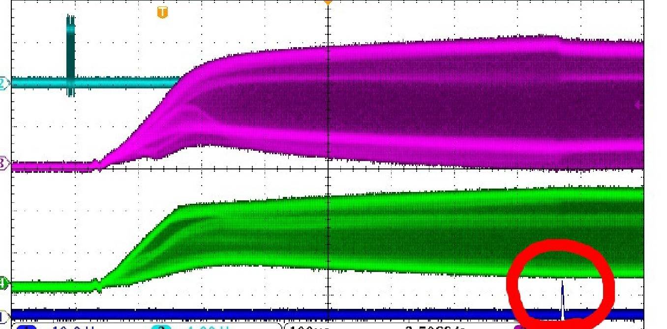
Attached the waveform. The switch pin open for a short period. I wonder if this is correct? Is there any way to keep it open longer? Or something wrong.

Waiting for your reply.

Thanks

Star

  • Hi Star,

    Welcome to the forum! I don't fully understand your question. Could you please clarify the following:

    • Which board are you using?
    • Which pin are you referring to (pin name)?
    • Could you please clarify what each signal on your plot is?

    Best regards,

    Leslie

  • Hi Leslie

    Thanks for your reply.

    1. The board was developed by customer himself , and only emb1428 was used. The picture of the real object is as follows.

    2. Currently the instruction is 0x90 and want to turn on cell1

    3. The waveforms from  top to bottom in the figure are CLK CEXT1, CEXT2 and sourse0 gate0

    Because the customer did not connect the MOS, then pull out 48 pin, so when measured the waveform of the switch, He connected the isolation probe to the gate and the source one by one. Is it right to observe in this way?

    He would like to know whether the waveform of my switch is correct, but is the opening time too short, and what is wrong with it?

    Thank you

    Star

  • Hi Star,

    The EMB1428Q is designed to work in conjunction with EMB1499 to be able to do active cell balancing. You need both chips to perform this function  because the EMB1428 sends commands to EMB1499, expects a handshake for it and also expects other signals to report back to the MCU. If the EMB1428 doesn't receive the expected signals from the EMB1499, it will create a fault and open all switches. To see more details about what I just described, please see "Normal Control Sequencing" section on page 18 of the EMB1428 device datasheet, and "Fault Reporting" section on page 19: http://www.ti.com/lit/ds/symlink/emb1428q.pdf   

    Regarding what signal to expect on the gate and source pins, please see "FET Driver Parameters" on page 6 of the device datasheet. VGSON is the driver output "on" voltage (VGATE-VSOURCE), which is typical 12.1V. If the signal is only staying on for a very short period of time, then more than likely you are seeing what I described above where the EMB1428 is waiting for signals from EMB1499, doesn't receive anything and therefore it goes into a fault condition and open all switches.

    Best regards,

    Leslie