This thread has been locked.

If you have a related question, please click the "Ask a related question" button in the top right corner. The newly created question will be automatically linked to this question.

BQ24725A: BQ24725A charge current adjustment

Part Number: BQ24725A

Hi TI,


We have issue here in charging our batteries: as the charging current gradually increased to 260mA by tuning the register setting, all looked OK, however the current stopped increasing when reaching 260mA and started to increase again after the charging current register increased to 0x1780~0x1800, please refer the table below:


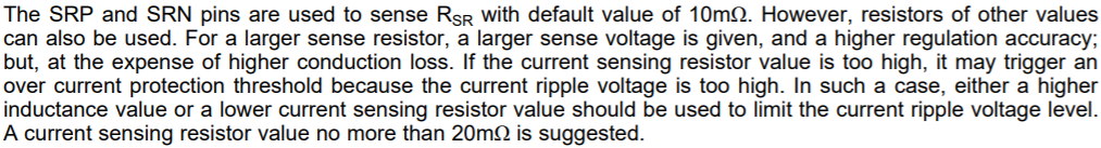
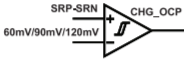
Just now sure if there are any sort of protection mechanism triggered in the charger providing the test result like this. Please note that we are using 0.15ohm output sensor in this BQ24725A charger design.


Thanks!


  • Hi Fan,

    Can you please share your schematic? Also, what are ADC modules 2, 3, and 4 measuring?

    Best regards,

    Angelo

  • Hi Angelo,

    Could you leave your email address to me? Just had the concern about posting the schematic in the forum.

    Thanks!

    Fan

  • Hi Fan,

    Sure, my email address is a-zhang2@ti.com.

    Best regards,

    Angelo

  • Hi Fan,

    Thanks for sending me your schematic.

    The issue may be due to your Rsr = 150 mΩ sense resistor value. The maximum sense resistor value that we recommend is 20 mΩ, as shown below:

    Also, please decrease C213 (the BTST cap) from 100 nF to 47 nF.

    Best regards,

    Angelo

  • Hi Angelo,

    If it is because of the sensor resistor, why does the output current reach 400mA after we set the current resistor to 0x1780~0x1840? The current ripple voltage should trigger the over current protection by then. The problem is we just couldn't set the output between 270mA and 400mA.

    Thanks!

    Fan

  • Hi Fan,

    I noticed that your ICHG "dead window" between 270 mA and 400 mA corresponds to charge current register values of 0x1000 - 0x17C0. This strongly suggests that the issue is related to your Rsr sense resistor value. As shown in the table below, a charge current register setting between 0x1000 - 0x17C0 has a different VOCP_RISE threshold from 0x0xxx and 0x1800 - 0x1FC0. This could explain why you only see a dead window between 270 mA and 400 mA.

    Please make the modifications I described in my last reply (decrease Rsr and the BTST cap). After changing those components, if there is still an ICHG dead window between 270 mA and 400 mA, then we can investigate this further.

    Best regards,

    Angelo

  • Hi Angelo,

    Thanks so much for the explanation for CHARGE OVER-CURRENT COMPARATOR, never noticed this parameter would impact our charging rate. As for the bootstrap capacitor, I will update the design, however I still have no idea how this could be related to our problem, because theoretically a larger capacitor will reduce the ripple brought to the switching node, which is positive. Could you provide more tips?

    Thanks!

    Fan

  • Hi Fan,

    A 100 nF BTST cap should also work. I just wanted to point out that this value is different from the 47 nF that we use in our typical application diagram and on our EVM. We do our evaluation using a 47 nF BTST cap, so we can be more sure of the BQ24725A's performance under these conditions.

    In general, a BTST cap slightly larger than 47 nF is fine. However, a BTST cap smaller than 47 nF would discharge more quickly and require more refresh pulses, which is undesirable.

    Best regards,

    Angelo

  • Thanks again, Angelo,

    I think based on the information you provided, we may explain what we observed here on our production line, however our technician also mentioned to me that the there were also several modules which output the value between 270mA and 400mA, could that be explained by the comparator performance difference?

    BR,

    Fan

  • Hi Fan,

    Yes, this behavior is probably related to your 150 mΩ Rsr value tripping the charge over-current comparator on some of your modules. Using a smaller Rsr sense resistor value should allow all the modules to charge between 270-400 mA. A smaller Rsr value will also increase your efficiency since there will be less conduction loss from the sense resistor.

    Best regards,

    Angelo