This thread has been locked.

If you have a related question, please click the "Ask a related question" button in the top right corner. The newly created question will be automatically linked to this question.

TPS61022: burns in high impedance input source condition

Part Number: TPS61022

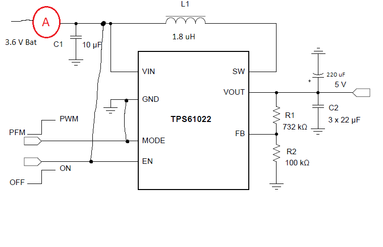
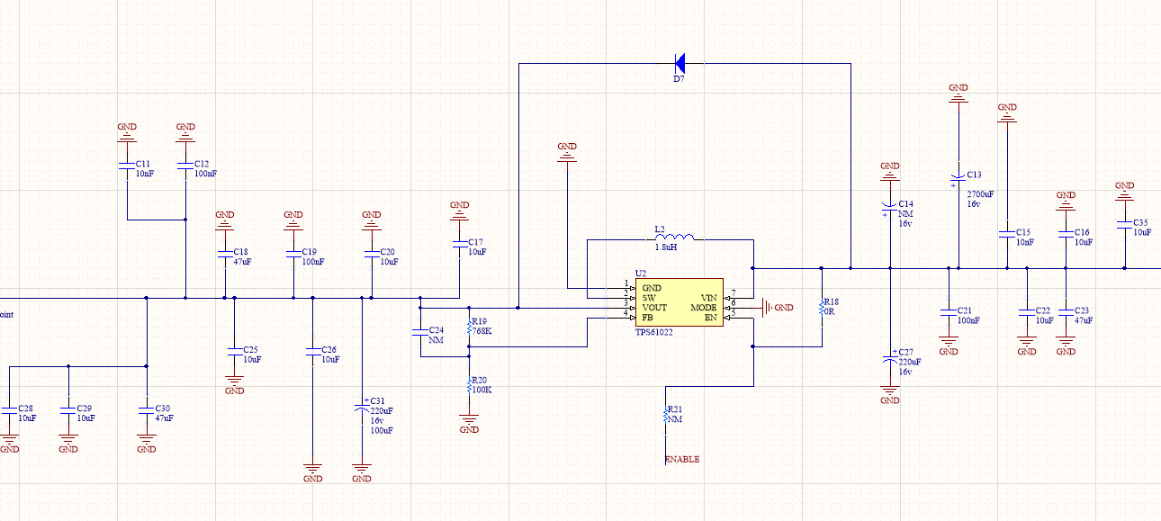
I use tps61022 and my design is exactly like the recommended design in the datasheet

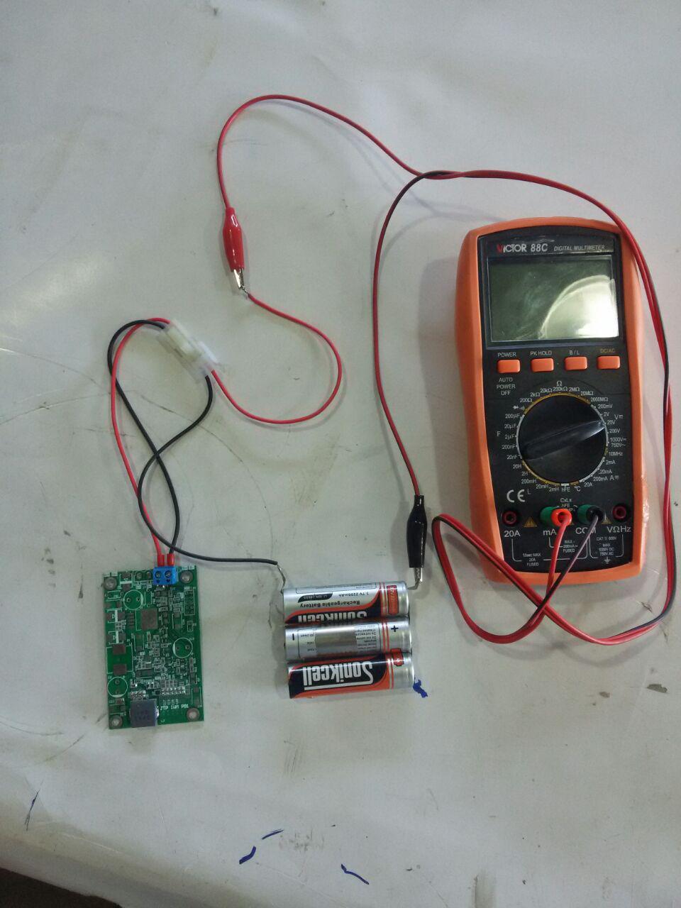
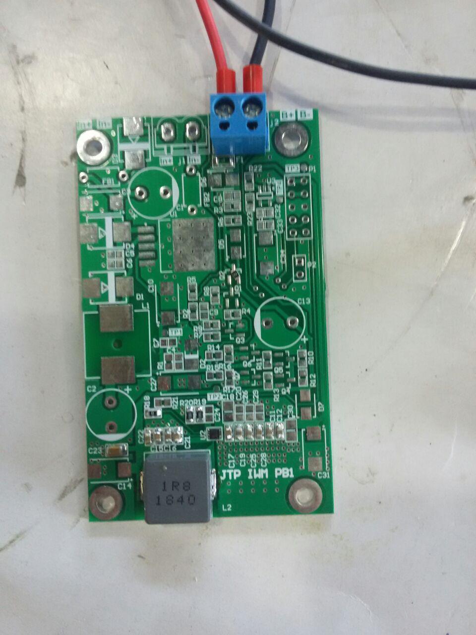
I connect a battery to its input and it works fine and gives me correct voltage (5.25V) and sufficient current. but when I want to measure the input current by putting an ampere meter on the input of the circuit, the tps61022 burns immediately and its SW pin connects to the ground. the series resistor of amper meter is 100 ohm. I want to measure no load quiescent current of tps61022 so for appropriate ampere meter range, its series resistor becomes 100 ohm.

why it is so? did you have such an experience? do you have any idea?

I will be grateful if you help me with this problem.

  • Hi 

    could you share the schematic and layout?

    please also the VIN waveform after putting an ampere meter.

  • after doing some expriment i found out the problem is 220uF output tantalum capacitor. when i removed this capacitor the problem solved.

    Also, I found out even without ammeter and by just connecting the battery directly to the circuit this happens and IC burns if the output capacitor be large.

    But I don't know why it caused TPS6102 burn. its datasheet said about minimum output capacitor but I didn't see anything about maximum output capacitor.

    Why it is so?

    can you please explain to me?

  • We didn't see this issue in our EVM. maybe it is related to the setup .

    1. could you share the layout?

    2. could you measure waveform of the VIN and VOUT when power up the circuit.

    3. could you try to disable the circuit through EN pin firstly before power up the circuit. enable the circuit using external logic signal after connecting the battery, 

  • this is my layout

    this is my schematic:


    I connect the battery directly to the circuit while a 10 Ohm resistor is connected to the output. the circuit works fine and there is no problem in start-up. but when I insert an 18 Ohm series resistor between the battery terminals and circuit the IC burns and SW becomes connected to the GND.

    unfortunately, I don't have a digital oscilloscope. 

  • what input and output capacitors did you use in your EVM?


    I am suspected to the 220uF tantalum capacitor which I put at the output.

  • Generally can choosing wrong input or output capacitors values bring such issues to boost converters?

    I don't expect high value input or output capacitors make such issues but it seems my problem is related to those.

    I removed 2700 uF input capacitor and seems the problem is solved and IC doesn't burn when I put a 10-100ohm series resistor between battery and circuit.

    can you please explain this behavior?

  • Hi Alireza,

    What's the purpose of D7 in your schematic and may I know why you put so big input & output capacitor?

    I'll try to replicate this test on EVM and let you know the result once I get a conclusion. Please be patient. Thanks.

  • Hi
    Thanks for your reply.

    In tps61022 datasheet page 19: For those applications with input voltage higher than 4.8 V, TI suggests adding a diode between the VIN pin and the VOUT pin to pre-bias the output before the TPS61022 is enabled.

    I hade these experiments with D7 unmounted and I remember it doesn't change the results.

    I used big capacitors in other to achieve high load and supply regulation. tps61022 supplies an LDO which supplies a GSM modem. also, I used big capacitors for EMC reasons and make my digital circuit more robust in high noise environments. do you think I indulged?

  • Hi Alireza,

    Can you take a picture of your hardware? I want to see how the board and power supply, input current sense resistor are connected, then I will do the same test with yours using an EVM today.

  • Hi

    This is my hardware. sorry for bad image quality. don't pay attention to the other parts of the circuit. they are related to other voltage levels and are unmounted and have nothing to do with the boost converter.

    when I put a bulk capacitor on C13 (2700uf electrolyte) the problem arises and the IC burns in high resistance input source condition.

    Also, I should mention that my boost converter feeds an LDO which feeds a gsm modem. the gsm modem max current consumption could reach to 2A during a burst transmission. the reason for using big capacitors is load regulation during these burst transmission. the other problem that I encountered recently is that there is a 100uf low ESR capacitor after LDO and each time I enable the LDO it drains a lot of currents and I see a 2v voltage dip in the output of tps61022 (converter has 250uf input capacitor and 60uf output capacitor and battery is directly connected to circuit ). can you please help me to achieve a better load regulation in these conditions?

  • Hi Alireza,

    I do the similar test using EVM in lab. Two 1000uf/16V aluminum electrolytic capacitors are soldered in parallel with input cap. Vin is 3.7V, Vo=5V at no load. Below is the startup picture:

    (CH1: Vin, Ch3: Vout, CH4: Iin)

    There is no issue and IC burn found.

    When you run this test, is there any load connnected? It would be helpful for us to analyze if you could capture the startup waveform.

    For better load transient performance, add a 100pF feedforward capacitor C24. It will increase the loop cross over frequency.

  • Hi Zack,

    Yes there is two tantalum capacitor at the output of IC in my secondary circuit (GSM circuit).

    Did you put any series resistor between the input source voltage and IC?

    How many times did you turn the IC on and off? In my experiments I found out burning may occur after plugging-in and out the connector for several times.

    How much the output capacitor is in your test? Can you please put two 220uf tantalum capacitors in parallel at the output and check if any rating exceeds during startup with both zero source series resistor and an 18-ohm source series resistor? 

  • Hi Alireza,

    Now the Cin is 2*1000uF and Cout is 1*1000uF aluminum electrolytic capacitor, Vin 3.7V, Vo 5V, at no load, I saw no issues during startup with both zero source series resistor and an 18 ohm source series resistor. I tried 10 times for each condition.

    Could you capture the startup waveform and share it with us?

  • Hi Alireza,

    I'll close this thread since haven't got any replies from you. You can post a new thread if you still have any questions. Thanks.