This thread has been locked.

If you have a related question, please click the "Ask a related question" button in the top right corner. The newly created question will be automatically linked to this question.

LM5170EVM-BIDIR: when use buck mode, input voltage is 48V, but the output is not 12V

Part Number: LM5170EVM-BIDIR
Other Parts Discussed in Thread: LM5170

Recently we have test the board(LM5170EVM-BIDIR), now I find an issue about the test steps, could you help me check the root cause? Thank you very much!

My test steps is like this:(eg: buck mode 48V to 12V)

1.     Provide the 48V

2.     Use J17-pins 5 and 6 to enable EVM, and provide 3.3V voltage

3.     DIR use J28 to realize

4.     EN1 and EN2 use J29,J30 and J25

5.     Use ISETA, and set J17-pins 11 and 12 voltage is 1.5V

6.     Then I observe the 12 VDC voltage is 24V(Up and down fluctuations), not 12V, so I don’t know why the result is this?

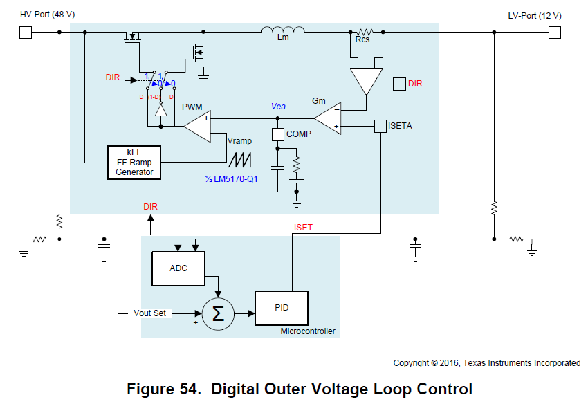
 The detail connect chart is like the picture.

The project is ergency, I will wait for your reply, Many thanks!

  • Hi User,

    Thank you for the picture, which help a lot in debugging the issue. I believe our colleague posted the same issue yesterday.

    You cannot use both J36 and external ISETA at the same time. J36 sets the ISETA signal by the voltage loop control circuit, and your external 1.5V override it.  When you force an ISETA, you make the EVM an current source, producing 60A output current.  But you have no load attached to the 12V port, this will raise the output voltage and high OVPB.  

    Please remove the 1.5V supply at the ISETA, then you will see 12V port regulates at 14.5V.  

    Also remember to close J3 (labeld as SYNC_R).  This disable the fault detection at startup and can allow the circuit operation in your setup.  

    Please read the datasheet and EVM for details.


    Best Regards,

    Youhao Xi,  Applications. 

  • Hello Youhao:

           Today I have tried to use onboard outer voltage loop control method(J36), the output voltage is 14.5. The issue is solved. But if I tried to add the load to the 12V, removing J36, the output voltage is 24V(Up and down fluctuations), not 12V, so I don’t know why the result is this? In the test, I use the resistance is about 9MΩ. I don't know how can I choose the load resistance? Could you please give me some advice about it? My detail connect line is like the picture.

    I will wait for your reply, thank you for your support!

  • I am afraid some fundamental understanding of using the part is missing. When you remove the voltage loop control, you lose the output regulation.  Not sure why do you want to run the circuit this way?  If you want output voltage regulation, you must have the voltage loop in place.

    If you just want to use the Lm5170 to implement a current source, then your load need to be able to sink the current that is produced by the converter. 

  • Thank you for your reply. I am sorry I cann't description our project target. In our project, we need the output voltage is 12V(buck mode), and 48V(boost mode). But in our board, when I use the onboard voltage loop control, the output voltage is 14.5V. If I want  to change the regulation level, should I change the resistor on the board? If it is right, which resistor should be changed? I am very sorry to trouble you again. Thank you for your support!

  • Understood. 

    For 12Vout, please change R78 from 4.42k to 5.36k.

    For 48Vout, please change R77 from 2.10k to 2.15k.  

    You may fine tune R78 and R77 to get the exact voltage.  

    Hope this help.

    Thanks,

    Youhao

  • Hello Youhao:

            If I want to use Lm5170 to relize the output voltage is adjustable(in the normal range). For example: when I use buck mode,need the output voltage is 15V or other values(not regulation). I think I should not to use the "Analog Outer Voltage Loop Control"(on board). Is it right? In the technical document I see a picture about "Digital Outer Voltage Loop Control"(the picture is below), should I use this way to realize?And how can I to connect the component? Thank you very much! I will wait for your reply!

  • Hi, 

    I think you duplicated the post.  I have answered to your new post, so lets close this one here.

    Best Regards,

    Youhao