This thread has been locked.

If you have a related question, please click the "Ask a related question" button in the top right corner. The newly created question will be automatically linked to this question.

TPS65150-Q1: schematic review

Part Number: TPS65150-Q1

Dear Team,

Could you please help check below schematic?

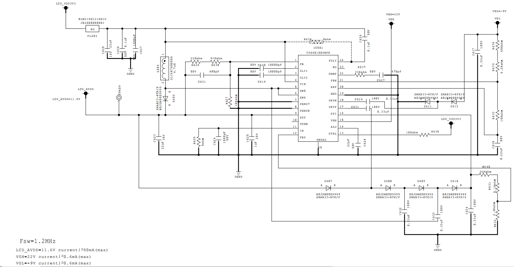
Input voltage is 3.3V, output LCD_AVDD=11.6V, 80mA. VGH = 22V, 0.6 mA. VGL = -9V, 0.6 mA.

Thanks & Best Regards,

Sherry

  • Hi,

    I have notified our expert regarding this topic. Please expect a response by 8/14/19.

    Thanks,

    Aaron

  • Hi Aaron,

    Is there any feedback? It has been one week, but I didn't get any response.

    Best Regards,

    Sherry

  • Hi Sherry,

    My apology about the delay in response as some of the team members were on summer holidays.

    I reviewed the schematics and it mostly looks good. I have following comments:

    -   With the feedback resistor values used for boost circuit, I calculated the feed-forward capacitor C621 value to be approx. 224pf. A standard value closest to this value should be used. Please see equation 7 in the datasheet for calculating this value.

    - Feedback resistor R633 for negative charge pump is recommended to be in the range of 39K to 150K. Smaller values load REF pin too heavily and larger values introduce stability issues. So please use a value in this range.

    R635 for CTRL signal should be a 0 ohm resistor.

    Kind Regards,

    Liaqat