This thread has been locked.

If you have a related question, please click the "Ask a related question" button in the top right corner. The newly created question will be automatically linked to this question.

UCC28700-Q1: Enable / Disable of UCC28700

Part Number: UCC28700-Q1
Other Parts Discussed in Thread: UCC28700, UCC28730-Q1, UCC28730

Hello,

We have a Flyback converter with UCC28700. Is there a way to enable / disable the UCC28700 like UCX84X Current-Mode PWM Controllers (pulling the COMP pin to ground would disable the UCX84X)?

If there is already a thread discussing this, can you please direct me to it.

Thanks,

Anand.

  • Hello,

    The easiest way to disable the UCC28700 is to use a series pass regulator to VDD. 

    1. Use a NPN transistor
    2. Connect Collector to source
    3. Resistor divider from collect to base to ground.
    4. Use a FET to short base to ground when you want to turn it off.

     Regards,

  • Hello Mike,

    Sorry for the very late reply and thanks for your suggestion.

    Can I use a similar series pass regulator for Enable / Disable of UCC28730-Q1 which has an internal start up current source.

    Thanks,

    Anand.

  • Hello Anand,

    I just got back from vacation and saw this and the more I think about this it may not shut down the device totally even with the UCC28700.

    The device will trickle charge and the VDD if the series  pass is pulled low.  To ensure this works put a diode from the NPN transistors emitter (anode) to the base (cathode).  This will ensure the device stays off even with trickle charging. 

    This should work with the UCC28730 as week.

    Regards,

    Mike

  • Hello Mike,

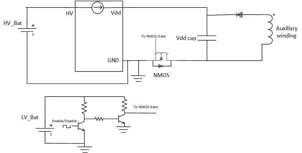
    Thanks. I just made a simple schematic of how the circuit would be with UCC28730-Q1. Please find it attached and request your opinion on it.

    I did not find high side enable disable using PMOS as a good option in this case.

    Thanks,

    Anand.

  • Hello Anand,

    That will shut of the FET but the FET and the IC will dissipate power until the VDD capacitor is discharged.  However, since there is no real switching of the power converter going on the VDD capacitor should discharge quickly.  This could work; however, you need to verify it in the lab to make sure the IC does not have excessive heating.

    Regards,

  • Hello Mike,

    Thanks for your reply. Your above answer has got me wondering as to whether the circuit would work. Even if the NMOS is turned off the body diode would still conduct to keep the IC working. The Vdd cap will not discharge as the auxiliary winding is still working.

    Regards,

    Anand.

  • Hello Anand,

    I thought the FET drain was connected to the drive not the aux return.  Use the FEt to pull down on the DRV pin and the circuit should work.  What happens is you will stop the fly back from switching that action will stop the aux winding from supplying power to the IC.  The drive will still be trying to drive current but will quickly discharge the VDD capacitor and shut down the device.

    Regards,

  • Thanks Mike. This helps me.

    Regards,