This thread has been locked.

If you have a related question, please click the "Ask a related question" button in the top right corner. The newly created question will be automatically linked to this question.

UCC21732-Q1: Undervoltage and Desat fault false triggers

Part Number: UCC21732-Q1
Other Parts Discussed in Thread: UCC21732

Hello TI Team,

We have a new project for passenger vehicle motor drive, where we tried to simplify our existing gate driver design using UCC21732. We built board and are using it on FF600R12ME4C module (half bridge) just for testing.

Three boards combined spins the motor just fine for now (not fully tested) except for occasional UVLO and desat trips.


We narrowed down problem where we can reliably reproduce it. SCH below:

PS voltage is +16V, -4.7V. On the PWM input is Rigol DG1022 signal generator. We can switch HS or LS or both IGBTs, same problem.
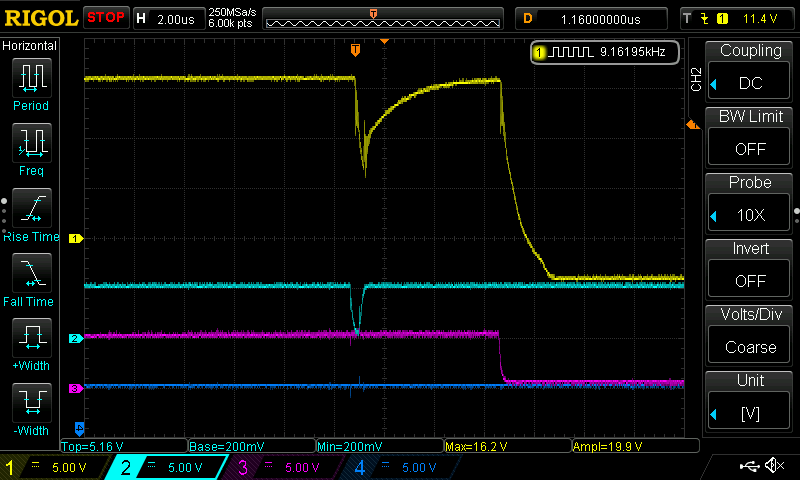
Scope screenshot:


CH1 yellow: PWM input
CH2 blue: IGBT Gate (differential probe between E and G)

With narrow pulse, approx. 300ns wide, UVLO fault happens. IGBT is turned off after 5us just like datasheet says (VDD UVLO off delay to output low). IGBT turns back on after 0.8ms, as per DS.

If we decrease pulse width even further we get desat fault. UVLO and desat faults happens only with high duty cycles (>99.4% @20kHz). We could not reproduce problem with low duty cycles (when signal goes high for short time).

Short circuit between E and C to bypass desat - no change. Short circuit between pins 2-3 - no change.

PWM frequency also doesn't matter, only pulse width.
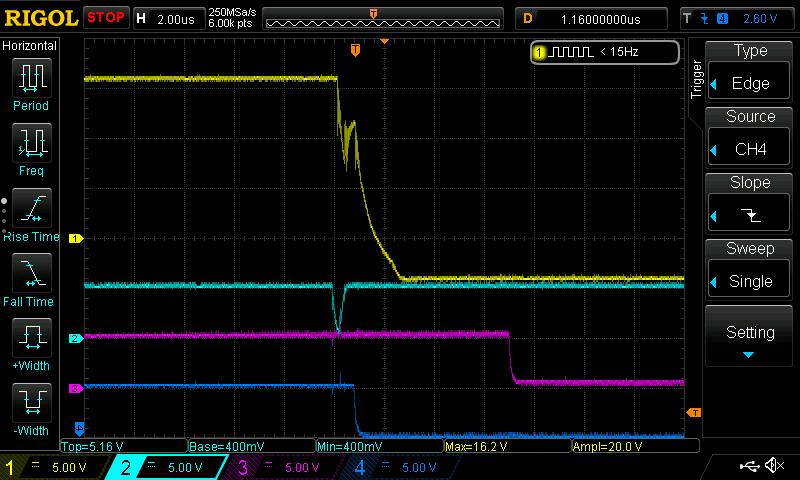
Zoomed in pic:

CH1 yellow: PWM input
CH2 blue: IGBT Gate

It looks like it happens when IGBT doesn't have enough time to fully turn off. Gate voltage manages to go down only to 4V.

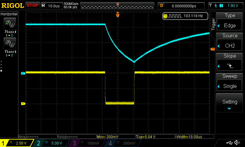
PS voltages two pics below:

CH1 yellow: Voltage between driver pins 3 and 5 (COM and VDD)
CH2 blue: IGBT Gate

CH1 yellow: Voltage between driver pins 3 and 8 (COM and VEE)
CH2 blue: IGBT Gate

PS voltages looks stable enough with sufficient margin to not trip UVLO levels.

We could reproduce the same problem with 10nF foil cap on gate, instead of IGBT, with pulses less than 200ns, so some of my colleagues expressed worries that noise on short pulses could be source of the issues.

So we removed IGBT and put 10uF cap on the gate. This should be slow enough to eliminate short pulses theory. We needed to modify PS (put a LOT of caps) for this to work. PWM frequency is set to 100Hz. Desat sense is shorted.

Normal operation (PWM pulse width >18us):

CH1 yellow: PWM input
CH2 blue: 10uF Cap (diff probe close to gate resistors)

Fault (PWM pulse width <= 18us):

CH1 yellow: PWM input
CH2 blue: 10uF Cap

UVLO fault triggers when gate voltage could not fall below 4V. If we decrease pulse width even further desat fault latches output to -4.7V.

We can provide more details if needed, please advise.


Kind regards,
Zoran Halić

  • Hi Zoran,

    Thanks a lot for your post and for including many waveforms. I will review these in detail as well as the schematic.

    At first I do notice that Q1 is a p-channel MOSFET, but it needs to be an n-channel MOSFET. Can you please change that and see if it improves your setup.

    Regards,

    Audrey

  • Hi Audrey,

    Thank you for your reply. You are right, active clamp doesn't work so we disabled it completely. All waveforms are without active clamp.

    One thing we noticed that in the waveforms above active clamp pin doesn't change its state. Gate voltage needs to drop below -2V for it to trigger, so we didn't bother with it until this is resolved. Still, we will retest with clamp enabled to check for any differences.

    Kind regards,

    Zoran Halić

  • Hi Zoran,

    Are you also monitoring the RDY and nFLT pins to show which fault is being triggered? I'd like to see those as well to determine which fault actually the output to go low. 

    Additionally, your DESAT circuit blanking time, according to my calculation, is <100ns which is very short for an IGBT. You would benefit by increasing C22 to 220 pF and/or decreasing the value of R32.

    Regards,

    Audrey

  • Hi Audrey,

    Active clamp is now working.

    Without active clamp:

    CH1 yellow: IGBT Gate
    CH2 cyan: PWM input

    With clamp:

    CH1 yellow: IGBT Gate
    CH2 cyan: PWM input

    However fault behavior is still the same.

    We are indeed monitoring fault signals which goes to the MCU.

    1st pic: normal behavior
    2nd pic: increased duty cycle when RDY starts to appear
    3rd pic: further increased DC until nFLT

    CH1 yellow: IGBT Gate
    CH2 cyan: PWM
    CH3 magenta: RDY
    CH4 blue: nFLT

    Waveforms above are with C22=1nF, changing capacitor didn't make any effect.

    Regards,
    Zoran Halić

  • Hi Zoran:

    Thanks a lot for the question. You are correct that the issue is because the off pulse is not long enough to turn off the IGBT module. We have improved the design and in the final production parts online now, you will no long see this issue. For the large IGBT module FF600R12ME4C, the equivalent Ciss during normal switching is about 150nF. With the Rg_int=1.2ohm, and the Rg_ext=2.3oh, the minimum pulse width to fully turn off the IGBT should be above 800ns. With 300ns pulse width, the IGBT cannot be fully turned off. In the final production parts, the driver will switch from OFF to ON status after the load is fully turned off. If inputing a short turn off pulse, the driver will extent the pulse until the load is fully discharged and then turn on.

    I also notice the gate resistance of CLMPE MOSFET is 100ohm, which can limit the driving strengh of the CLMPE pin. You can use a 2ohm resistor here instead.

    Thanks and Regards,

    Susan

  • Hi Susan,

    We clamped short pulses in SW and everything works just fine. It's good to know that it is fixed in HW too.

    Thanks for support, detailed explanation and great suggestions, you guys are awesome. ;-)

    Kind regards,
    Zoran Halić