Other Parts Discussed in Thread: BQ25703
Hi there,
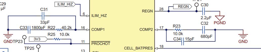
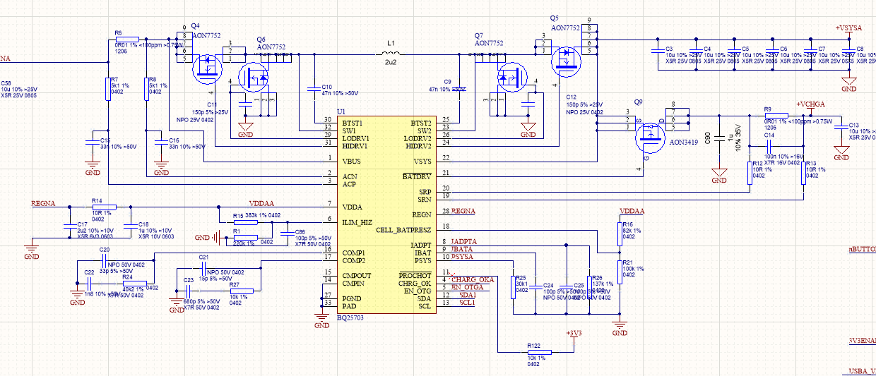
I am working on a design which is essentially a USB-C battery bank, with a 3S battery. Attached is a snippet of the schematic design, which has basically been lifted from the USB-C power bank example provided by TI.

The unexpected behaviour I am seeing occurs when the design is being used to to power a UFP from the battery in USB OTG mode (i.e. discharging the battery), using the BQ25703 in reverse mode as a step-up converter (stepping up from Vbat = 12.6V up to Vbus = 20V in the examples shown below).
There are a few observations I'd like to discuss:
1) There is audible noise coming from the circuit (from the inductor I believe) at low to medium loads up to around a 500mA load. Up to this current, the audible noise is an irregular clicking noise. This increases in frequency as the current increases, and then suddenly stops at around 500mA after which point it seems to never re-occur. My first thought was that this would coincide with the PFM vs PWM modes of the IC, but I have enabled the EN_OOA option, with no noticeable effect.
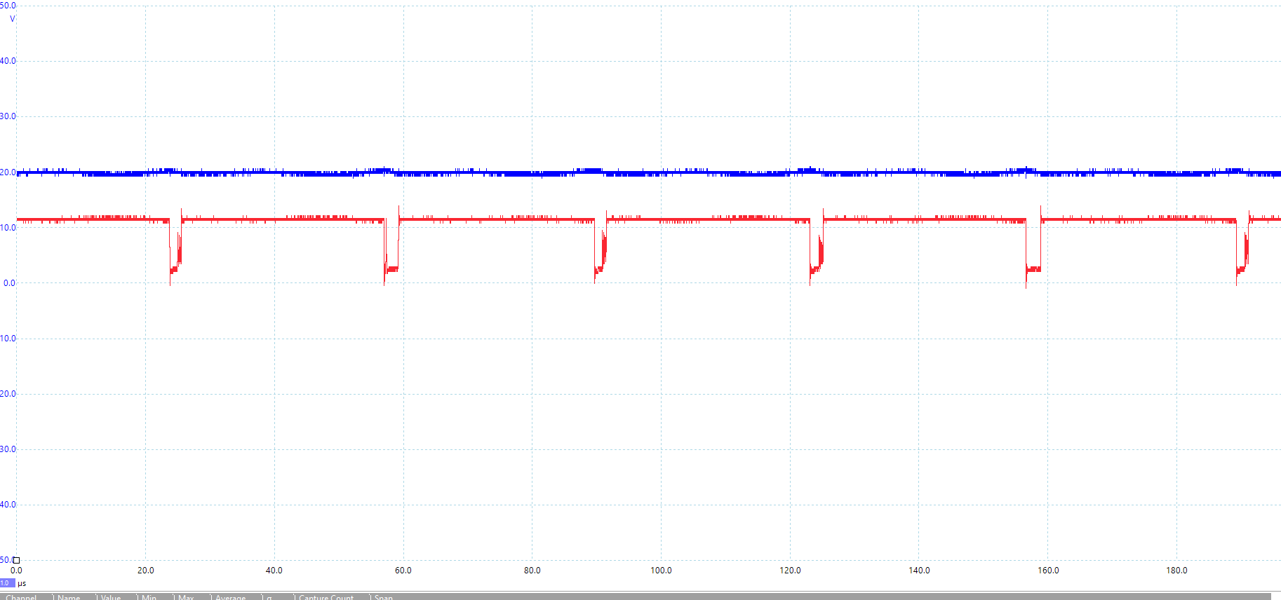
2) At these low output currents (up to 500mA), the output voltage of 20V is very unstable. I have taken some oscilloscope plots to demonstrate this behaviour:
200mA output current, SW2 and SW1 shown:

200mA output current, SW2 and VBUS shown (as you can see, the 20V output rail is extemely unstable):

1A output current, SW2 and SW1 shown:

1A output current, SW2 and VBUS shown:
The 1A plots above are as I would expect, but at 200mA the behaviour is strange, and the 20V output very unstable.
3) The 2u2 inductor seems to get very hot. Even at output currents of 1 or 2 amps, the inductor body gets up to around 60 - 75 degrees celcius. This seems on the high side to me, and makes me concerned about using the design to source 60W or more as the design should be capable of. Note - I have tried a number of inductors, as explained later. Side question - does TI recommend heat-sinking this switching inductor on their battery bank designs?
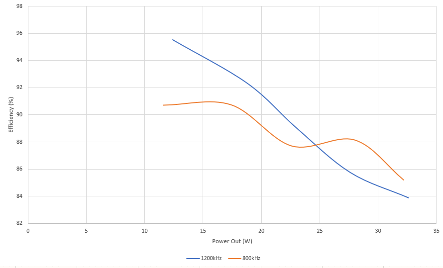
4) The efficiency is not as I would expect. Please see the plot below for efficiency performance at both 800kHz and 1200kHz operation - at lower power they seem to be as I would expect, but as the power output increases, the efficiency seems to tail off quite rapidly, whereas the datasheet states that the efficiency should remain above 94% in this power range for a 3S battery and USB OTG of 20V.
My assumption is that all 4 unexpected symptoms above stem from the same issue, and I am wondering if you had any ideas what this issue could be?
Please note that I have tried several 2u2 inductors (as I was concerned about DCR, saturation current etc), with the only noticeable difference being that the the one with an over-rated saturation voltage (Vishay Dale IHLP3232DZER2R2M01, Isat=23A) didn't seem to get quite as hot as the others.
Thanks for reading,
Iain.