This thread has been locked.

If you have a related question, please click the "Ask a related question" button in the top right corner. The newly created question will be automatically linked to this question.

BQ76940: bq78350-r1

Part Number: BQ76940
Other Parts Discussed in Thread: BQ78350-R1, BQSTUDIO

i have a similar question sir and will be glad if you answer..,

till date we have worked on the IC BQ76940 everything was good.but today when we have disconnected the cells and reconnected and applied the boot signal ,the output voltage across the REGOUT pin is around 0.4v and it must be 2.5V ,voltage across CAP1 pin after booting is 3.3V. IC is getting heated up .

what might be the problem please help us ...

if you could ,please provide us the internal circuit diagram of the ICBQ76940.

THANKS IN ADVANCE.

  • Hi Pavani,

    It sounds like the part or a support component was damaged during cell removal or connection.  Check for supply to the REGSRC pin and current into the pin.  REGSRC supplies the REGOUT regulator and FET drive as well as some internal circuitry.

    For diagrams see the block diagram in the data sheet http://www.ti.com/document-viewer/BQ76930/datasheet/functional-block-diagram-slusbk22474#SLUSBK22474 or various diagrams in http://www.ti.com/lit/pdf/slua749  

  • thank you sir for your response..,

    upto our knowledge we think the part has damaged sir ..but if the part (BQ76940) has damaged the output must be zero but its showing 0.4V why?

    is there any other way to reuse the same IC. 

    THANKS IN ADVANCE  

  • Hi Pavani,

    A damaged part may have various resistive paths inside the circuit which could allow the part to regulate at the low voltage or limit at that voltage.  I expect you have already checked the net for contamination or unexpected conductors on the net, but an external short could also limit the voltage.  You might try lifting the REGOUT pin before replacing the IC to confirm if it is internal or external.

    If the IC is damaged I don't know of a way it might be used.  While the IC is removed be sure to check for unusual voltages present or shorts on nets or components.  Other than a short of REGOUT to GND or a high voltage, short of the REGSRC to high voltage including shorting of the source follower FET might be suspected.

  • Hi sir,

    i didn't understand this sentence "you might try lifting the REGOUT pin before replacing the IC to confirm if it is internal or external." what is meant by lifting REGOUT pin?

    another issue i wanted to know is when we send the command 0x0022 then FET-EN is set this is fine. in datamemory-->settings-->manufacturing-->mfg status init-->there is FET-EN what happens when we set that bit?

    when we set that bit and LED EN bit in mfg status init ,and returning to the registers view and refreshing then the FET-EN bit becomes low and the LED EN bit remains in the same state(high).

    could you please explain what is that mfg status init setting?

    thanks in advance 

    pavani.

  • Hi Pavani,

    "Lifting the pin" would be to de-solder the pin and bend it up slightly off the trace to see if the short is internal to the IC or on the remaining net. Sometimes this will remove a solder short under the IC pin and both the IC and the net will look normal.  With the pin lifted you can see if the REGOUT goes to its normal voltage and the IC has a normal temperature.  If it does the part may not work well since it does not have a capacitor on the REGOUT.  Similarly you can see if the REGOUT net on the board has an unusual resistance, or draws unusual current when powered by an test source at its normal value.

    When you set the FET_EN bit in the Mfg Status Init parameter, after the checks for normal conditions at power up the BQ78350-R1 will turn on the FETs.  If you leave the FET_EN bit low the part will not turn on FETs after the power up checks even though things are normal and FETs will not come on until the ManufacturerAccess command 0x0022 is sent.  Notice though in table 17-2 of the technical reference manual http://www.ti.com/lit/ug/sluubd3d/sluubd3d.pdf  that command 0x0022 is not available when the pack has been sealed.  The commands are good for testing in evaluation or during manufacturing, but the settings read from the Mfg Status Init parameter are best for the final product.

    The bits in Mfg Status Init are additive, the BQStudio tool will allow setting a single bit.  This can also be done with your own production system using a read/modify write to change 0x0010 to 0x0210.  See the technical reference section 12.1.1.  Another way to describe this may be that the Mfr Status Init parameter in data memory is copied to the Manufacturing Status register at reset.  The part behavior is controlled by the Manufacturing Status register which can be modified by various commands before the part is "sealed".

    Hope this helps.

  • thank you sir

    what is meant by device SHIP MODE?

    difference between ship mode and seal mode .how to come out of those ?

    thank you 

    pavani

  • Hi Pavani,

    The BQ78350-R1 describes power modes in the technical reference manual http://www.ti.com/lit/pdf/sluubd3  section 8 as normal, sleep and shutdown.  In shutdown it puts the BQ76940 in its ship mode to turn off power. 

    Ship mode is a power state where the BQ78350-R1 is turned off, and most of the BQ76940 is turned off except the boot detector. 

    To get out of ship mode boot the BQ76940 with the rising edge to TS1.

    Seal mode of the BQ78350-R1 is a security state where many commands are not allowed and configuration can not be changed.  This protects the settings in the battery.  See section 11.5 for information on security modes.  Once the BQ78350-R1 (or the battery) is sealed it is more difficult to make changes since the key must be entered after each reset.  As the designer of the battery you can enter your own key and make changes, and but normally the key is entered at the end.  The keys can be confusing so it is advisable to work with one to get a good understanding of how to work with it using the default key and how it will work for your situation with your own key and a part you can discard if needed.

    To get out of seal mode send the key as described in section 11.5.2 and 11.5.3, but it will return on reset.  You can reprogram the part with the firmware to get out of sealed mode but you will need to re-enter your parameters.

  • helo sir,

    1.even the auto refresh and scan is  ON ,the dashboard is not reading the values continously why?

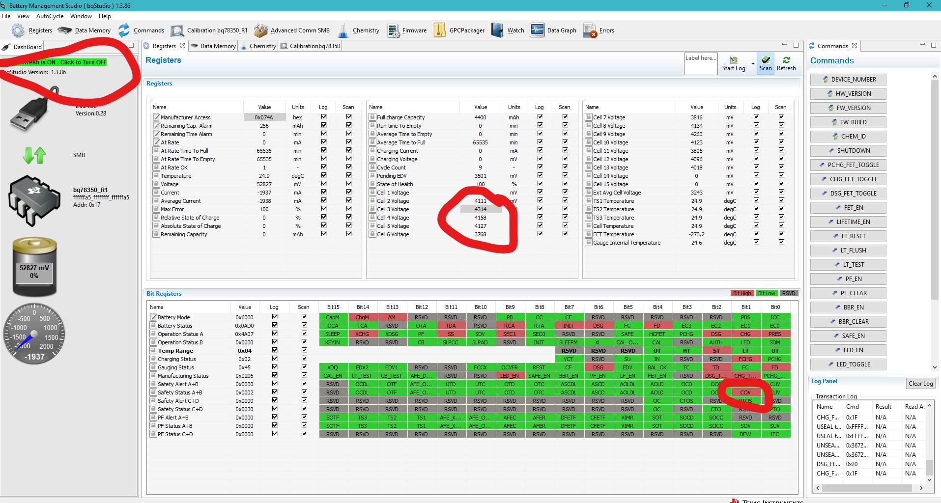
    2.when we connected our pack to the board in the morning for first time then the voltage values are shown on the display correctly.it is in complete operation since morning now in the evening when the cell3 voltage is dropped to 2800mv it is still reading the value which is in the morning and it is creating COV fault and unable to perform any function rightnow.i think they must change according to the state of the cell but no change in those cell voltages.what could be the reason?  

    3.another issue we are facing is that, when the device is in normal operation the FETs are turned ON and it is working good. but when we are charging the device,the CHG FET are turned OFF and DSG FETs remains ON. again when we remove the charging to the device both CHG and DSG FETs are ON. since the CHG FETs are turned OFF during charging ,will it allow charging or not? if this is wrong,then how the CHG FETs remains ON even during charging.(this issue is not shown in the image).

     for the 1st and 2nd issue,i m posting the image ,so that u can understand the problem easily.

  • Hi Pavani,

    1. I don't know, you will need to figure out why.    In the figure somthing is not right since the device number shows fff...  this should read 1e9b..., see the EVM user guide http://www.ti.com/lit/pdf/slvu925 figure 10.  Re-start BQStudio and see if it is correct.

    2. The data looks wrong.  If it is not showing actual cell voltages, you are not getting current data. 

    3. Yes, the device has body diode protection.  If you have charged to a COV condition and the charge FET is off, the charge FET will turn on again with sufficient discharge current.   It takes the part time to recognize the current and respond with FET control.  Your system should prevent charge or discharge, if you connect both and they can cycle, you can trick the part into charging periodically as your discharge tricks the battery into turning on the body diode protection.

  • how to enable the ADC in bqstudio software. as there is a provision of enabling ADC_EN in bq76940evalsoftware.

  • Hi Pavani,

    BQStudio talks to the BQ78350-R1.  In a system with BQ78350-R1,  it controls all features of the BQ76940.  There is no ADC_EN available, the BQ78350-R1 controls it as needed for operation.  Any time voltage is read by the gauge ADC_EN will be set.

  •  thank you sir,

    as mentioned in the TRM there are two ADC's one measures current ..,in our application current measurement is continuously reading .the second delta-sigma ADC which measures the individual cell voltage and temperature measurements ,which our gauge is not measuring. what could be the problem? are we missing any bit to set to measure the cell voltages and temperature?

    i think it would be helpful if i post our srec file.3618.BMS 4-9-19.gg.csv 

  • Hi Pavani,

    If you have cells set in the AFE Cell Map, which you do, they should be measured.

    The BQ76940 monitor does not provide voltages if it has an XREADY fault. If the monitor has a fault the gauge will quietly try to fix it and you may not know unless you have enabled observation.  

    You might look for the AFE_XRDY bit in the ManufacturerAccess() 0x0052 PFAlert, or read the status register from the monitor using ManufacturerAccess() 0x0058 AFEStatus, see the TRM.  If you have a XREADY fault, find the problem with the power and correct it.

  • hi sir,

    cell voltage values are read only when the pack is connected for the first time .

    theres no AFE_XREADY bit set either in PF alert nor in PF status. still what might be the problem?

    is our srec file which i posted is correct or any settings to be changed sir?

  • Hi Pavani,

    Your gg file reads voltages fine in an EVM, voltages change when the supply is adjusted.  If the file is not operating on your board perhaps the issue is in calibration data which is not normally copied from part to part.

    If you think your gg file has caused some problem, restore defaults to confirm operation of the board, then add back the settings until you find something which stops the ADC.

    You will need to determine if the settings are appropriate for your design.

  • hi sir,

    1.the percentage that is shown in the gauge in dashboard is related to what ?is it charging and discharging percentage or anything else? though our pack is fully charged the percentage is still 1% what is the reason?

    2.when the % in the gauge reaches to 0 and when the FD bit is set then the load must be cutoff i.e turn off the FETs but this action is not taking place .why?

  • Hi Pavani,

    The gauge must be set up properly to work well.  It does take some work.  See the technical reference manual http://www.ti.com/lit/pdf/sluubd3 and the gauging tool http://www.ti.com/tool/GPCCEDV .

    1. It sounds like the capacity set in the gauge is smaller than the battery attached.   Also you might consider the CSYNC bit to set 100 % capacity when charge termination occurs if desired.

    2. See the settings for the flags and FETs in the technical reference for what is possible. FETs normally turn off for safety events rather than gauge status.

  • Sir,

    we have set the CUV Threshold:3500mv recovery :3800mv. but when we have connected the load and started discharging the battery pack, even when one of  the cell voltages is dropped to 2600mv ,FETs are not turned OFF . and the system is not going to protection mode. why? but in TRM pg.no 21 section3.2 represents that it should detect the fault and doesnt allow further discharge. 

    similarly COV protection is also not detecting. what might be the reason ?

    thanks in advance.1667.cuv 19.gg.csv

  • Hi Pavani,

    To determine the cause of a misbehavior like this you must know how you have constructed your circuit and enabled the FETs.  In the gg file the settings look correct, COV and CUV are enabled, the thresholds and delays are set, and the FET_EN is enabled so the gauge can control FETs.

    Some things to check might be:

    • If the FETs work.  You might test before the voltage run.
    • If the gauge log sees the voltage change
      • If the gauge does not show voltage changing look for the PF ALERT or PF STATUS for AFE problems
    • If the gauge log shows the Safety ALERT and Safety Status change to CUV or COV.
    • If the gauge log shows the Operation Status CHG and/or DSG switching

    XREADY is not enabled as a PF in Settings Fuse PF SAFE B, if the system develops an XREADY fault after voltages are read once they may report the same value.

    Settings Fuse PF SAFE B
  • only one thing the guage does not show voltage changing and we dont have PF ALERT or PF STATUS BITS set.

    we are not knowing why voltage values are not refreshing.

    anymore  help will be highly appreciated from yourside.

    thankyou 

    pavani. 

  • Hi Pavani,

    If you are looking at BQStudio be sure you are scanning.  A log will start scanning, so if you are seeing voltages not change in a log then the gauge is not seeing them.

    You might see if the I2C pull up resistors have been lost so that the gauge no longer can talk to the BQ76940, but often this will cause loss of SMBus communication.

    If the BQ76940 has an XREADY fault it will not update voltages.   XREADY is caused by missing voltage on the CAPn capacitors or excessive noise on the system.  If one is occurring, fix the problem. While it is disruptive to the gauge you may need to read the BQ76940 status register during operation to see if XREADY has occurred.  If yes, fix the problem.

  •  today only we have placed the pull  up resistors near 3rd and 4th pins of bq78350-r1. but still no change in voltages .

    we dont have XREADY fault also sir. still what might be the reasons for disturbing the communication between bq78350-r1,bq7

  • Hi Pavani,

    The part works when implemented and installed correctly.  Beyond the causes mentioned I don't know why it would not work.  Check workmanship on connections, check the design based on the data sheet, EVM, and various reference documents.  Be sure power is remaining on and that the part is communicating.  Inspect the SMBus lines and I2C lines to determine what is the problem.  Be sure the PC has not become busy and ignoring the BQ78350-R1 or interface.

  • after IFC bit in PF status is set,from then onwards the CUV bit is set though we dont have any cell undervoltage .

    how to clear that CUV fault?

  • Hi Pavani,

    IFC is a permanent fail condition.  See the technical reference manual http://www.ti.com/lit/pdf/sluubd3 section 4.1 

    Notice that the FETs are turned off when this condition is detected and charge or discharge should be prohibited. 

    If the instruction flash is corrupt, the part will not be able to operate.  To recover from this condition reprogram  the gauge.

  • hi sir,

    in sec 11.5.1 it is mentioned that when the device is sealed standard SBS functions have access and extended SBS functions do not have access..what are those standard and extended SBS functions? is this the reason for cell voltages not varying continuously? or whether  device reset(sec 17.2.33) is anything responsible for cell voltages not varying?

    however we have cleared the problem after changing the IC BQ78350-R1 we have neither RESET nor SEALED the device till now and our board functions are going good. 

    now we wanted to know exactly what will happen if SEAL and RESET commands are given.

    thank you 

    pavani.

  • Hi Pavani,

    I am closing this thread since it looks like you copy/pasted the same question to another thread which I have already answered. 

    Regards,

    Matt