This thread has been locked.

If you have a related question, please click the "Ask a related question" button in the top right corner. The newly created question will be automatically linked to this question.

TPS548D22: loop stability question

Part Number: TPS548D22

Hi,

we met some problems with TPS548D22, attached is the design schematics of our application, could you please help to check below items?

1, help to review the schematic, to double confirm if there is any design weakness

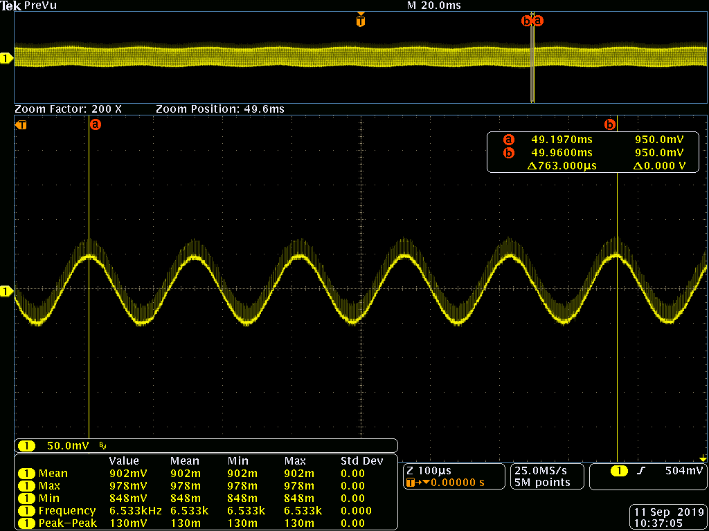
2, usually our output inductor has 2-3 sources, with one of them, there sometimes will be low frequency oscillation on the output voltage, you can find waveform through the attachment, do you believe this is caused by insufficient ramp compensation? As the failure will disappear if we tune the ramp compensation from R/2 to R. AND can I know how much inductance tolerance can our VR design tolerate, is there a way to calculate it?

3, sometimes it only appears at high temp. but there will be similar oscillation at power up when in normal temp, can you help to explain how this will happen? Or what parameters may impact this? Output inductance or other components?

4. seems when inductance is becoming large, the low frequency oscillation will occur easily, and tuning the compensation to R will address it. So my question is if there is paper calculation to verify if increasing inductance to 1.2uH will induce such kind of instability? Thanks. 

  • Harry Zhang,

    Yes, it is possible that the oscillation you are seeing on the output is related to the internal compensation ramp.  The D-CAP3 compensation loop used in the TPS548D22 converter is sensitive to the L-C filter resonance frequency, and phase delay between the inductor current and the output voltage ripple.

    1) The inductor seems extremely large for a 40A device switching at 650kHz.  The inductor ripple current is just 1.3A.

    That will heavily limit the rest of the circuits performance.  I would generally recommend a ripple current of 25 - 40% of the full load current.  I can't see the full load current on the schematic, but with a 16A OCP, I would think it would be at least 12A, so I would recommend looking for an inductor about 1/3 the current size.

    2) The Output filter looks like it's 2x 470uF electrolytic capacitors plus 5x 100uF ceramic capacitors 5 22uF ceramic output capacitors.

    That should be sufficient capacitance for either a 1.0uH or 0.3uH inductor, but the response is likely to be much better with the lower inductor value.

    3) The current L-C filter resonance frequency is about 4kHz, which is likely too low for the internal compensation zero, and likely why the loop is oscillating.

    Is there any chance you could reduce the inductor from 1.0uH to 300nH?  That would increase the L-C resonance frequency and phase delay

    Also, how are the remote sense lines run? 

    Is there additional VOUT capacitance at the load that is not shown on the schematic?

    Additional trace inductance and remote output capacitance inside the regulation loop can also contribute to compensation issues by adding additional delay between the switch-node and the regulated output current, which can also cause this kind of low-frequency output oscillation.

    For a 0.9V output, is there a reason you are not using the 0.9V reference voltage?  If you change the VSEL to ground resistor from 4.64k to 37.4k and remove the RSP to RSN divider resistor, the reference voltage will be set to 0.9V and you will remove any resistor divider error from the regulation accuracy of the output voltage.

  • Thanks Peter. 

    your reply is useful to me and i will try your suggestions. let me answer your question first:

    1. Imax=11A

    2. we have another 1000uF caps outside this schematic page. 

    3. remote sense is from the load side.

    and i'm still confused with something:

    1. which the zero frequency of 1/2R, R, 2R, 3R ramp compensation?  and what the relationship LC resonance frequency and zero frequency should be?

    2. do we need to measure bode plot to judge if phase margin and gain margin are enough? because it's COT controller.

    3. if we use 1uH and R ramp compensation (now we use 1uH and 1/2R ramp compensation), no oscillation happened, can i think internal compensation work well and it's stable? 

    thanks,

    harry 

  • Add two question:

    1. If I keep 1uH inductor and reduce caps such as 1x 470uF electrolytic capacitors plus 5x 100uF ceramic capacitors 5*22uF ceramic output capacitors. can i use R/2R/3R internal ramp compensation to increase our loop stability?

    2. if i use 400nH inductor and keep all caps and 1/2R internal ramp compensation, do you think it's stable?

    thanks,

    harry 

  • Harry, Andrew and Yakun,

    I am going to consolidate my responses to

    https://e2e.ti.com/support/power-management/f/196/p/840238/3109341#3109341

    and

    https://e2e.ti.com/support/power-management/f/196/p/840357/3109347#3109347

    Here.

    I am working on answering the questions from these three posts together.  I should have that finished tomorrow.