This thread has been locked.

If you have a related question, please click the "Ask a related question" button in the top right corner. The newly created question will be automatically linked to this question.

BQ25606: Heating issue

Part Number: BQ25606

Hi Team, 

I have a customer who is using the bq25606 in a project and is having issues with some fault testing:


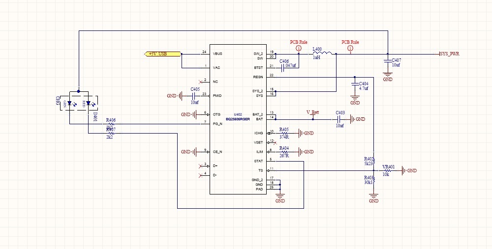
In my project I used the BQ25606 to charge a Li-Ion battery with protection circuit. For the first fault tests (Single Fault Condition), I short-circuit the capacitor to PMID (then the battery is plugged in). This is ok, because nothing gets too hot here. However, if I then remove the short circuit (de-energized), the IC becomes about 200 ° C hot (about 1.2 amps at 3.7 volts battery voltage). This battery power is unfortunately in the range of my operating current, so that I can not recognize / interrupt this current flow.

The error in this form is a fail for my first error tests. Can you tell me why that is? What is the issue with the BQ25606? Are there any recommendations to prevent this?

Regards,

Mihir

  • Hi Mihir,

       Is customer shorting PMID to GND and then removing short? Can you describe what customer means by short circuiting capacitor to PMID? 

  • Hi Kedar,

    Sorry for the confusion. The customer has a 22uF Cap between PMID and GND, and then simulated shorting the PMID to GND. However, once the short is removed, the IC gets very hot.

    Regards,

    Mihir

  • Team,

    Do you have any feedback for me?

    Regards

    Mihir

  • Hi Mihir, 

       I will perform the test on the EVM and get back to you with results on 9/26.

  •  How timely to see this article!  I am having a very similar issue as Mihir.  The BQ25606 appears to be connected properly.  I was looking for 1.89A charge current into a 4.2v 1S3P 6600mAh battery.  With the battery connected, and no external power (USB), the BQ25606 gets very hot.  It seems to supply power to the rest of the circuit just fine, but it is drawing 1.3A to supply a little more than 100mA!  After reading Mihir's post, I tried shorting PMID to ground, instead of running through the 10uf capacitor I am using, and sure enough, the chip instantly cooled off.  However, if USB is plugged in while shorting PMID to GND, current draw on the USB port quickly climbs to 3.98A.  Unsure of what the issue might be, but I have several identical boards all doing this exact same thing.  

    For reference, I am using an ILim resistor of 267Ohm, and an IChg resistor of 374Ohm.  I have attempted to change the inductor with various values between 1uH and 2.2 uH.  Always get the same result.  OTG is grounded.  CE is grounded.  I am using the temperature compensation circuit (TS), straight out of the data sheet and TI application guide, using the recommended thermistor, even.  

  • Hi Kedar,

    Did you have a chance to perform the test?

    Regards

    Mihir

  • I ran more tests.  If the inductor shorts or opens, it will destroy the BQ25606.  Replacing the inductor for one rated for higher current, and then replacing the BQ25606 with a new one solved the issue for us.  We ended up using a Delta Electronics 1uH/4.5A 0806 package inductor, part number HTEK20161T-1R0MSR.  Simply replacing the inductor did not fix the problem on a unit where the BQ25606 was already getting hot, but it seems to be preventing any other BQ25606's from failing.  Once we replaced the inductor and any BQ25606 that was heating up, there have been no further issues with those boards, either.  

  • Hi,

    Please note the following recommended operating conditions. The device operations should not exceed the max values listed in the table below.

    Thanks,

    Ning

  • Ning,

    Could you please let me know which spec is being exceeded in this case? The charging current limit is not being exceeded?

    Regards

    Mihir

  • Hey Mihir,

    You are likely exceeding both the ISYSOP specification and the IIN specification when you short PMID to GND.

    The HSFET of the buck converter will allow the battery to discharge completely into the short on PMID as well as the adapter. This can likely destroy the internal HSFET, which could mean a short between the PMID and SW. You can likely measure this on your board that sees the issue by performing a diode continuity test (will unpowered) between PMID and SW. While unpowered, the body diode of the HSFET should block current from flowing from PMID to SW. 

    It is also possible that a high di/dt from the sudden removal of the short caused a large voltage spike that exceeded a pin's absolute maximum rating, especially if the input or battery leads are long.

    Regards,

    Joel H