This thread has been locked.

If you have a related question, please click the "Ask a related question" button in the top right corner. The newly created question will be automatically linked to this question.

BQ76PL455A-Q1: BQ76200 EVM design refernece

Part Number: BQ76PL455A-Q1

hai sir,

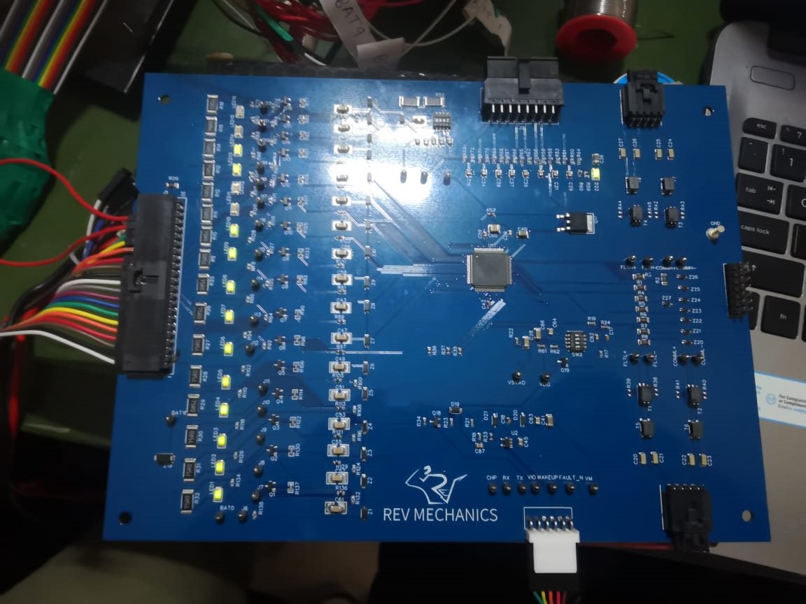
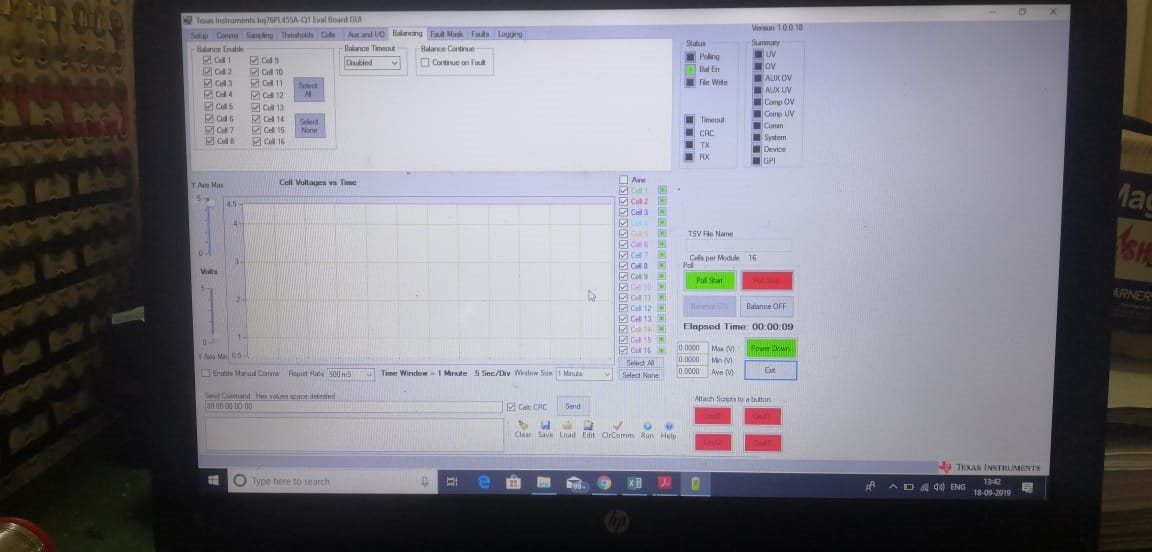
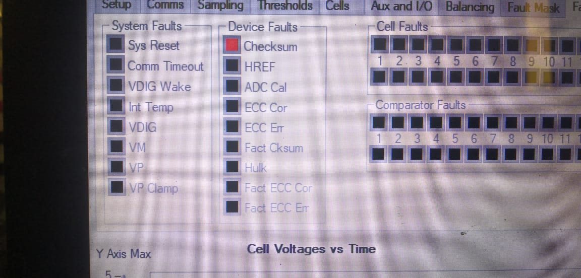
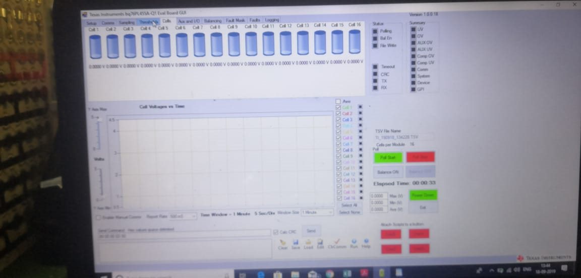
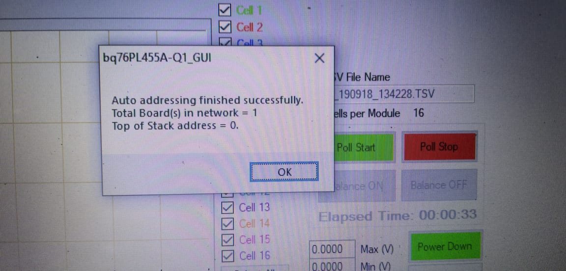
i have designed the BMS board as per the EVM refernece design and i am using only 1 board.The board is detected by the GUI but i am voltages of the cells are not visible in gui and the leds corresponding to the balancing circuit is always on as the cels are connected.And as a try t pool file write is showing red and device column , checksum is showing error.I also checked the voltage across test point the voltages are correct  I have not changed the register configuration.

  • Hi Shaheen, 

    I recommend to start by making sure all the power pins are powered up correctly at the correct voltage. Please measure all the power pins and see if they are at the right level (TOP, V5VAO, VDIG, VIO, VM, VP, VREF). You can see the expected voltage levels in the device datasheet in the Electrical Characteristics table starting on page 9:

    http://www.ti.com/lit/ds/symlink/bq76pl455a-q1.pdf

    Best regards,

    Leslie

  • hi mam

    thanks for taking time to look into the issue.

    i have checked all the voltages and i have seen that in datasheet at VM they say its -5V charge pump but when i measured in my board it showing 0.3V output between VM and GND. My tx and RX are working fine and i am also able to get the die temperatures but not able to obtain voltages of the cells. I have connected 13 cells and shorted 13 cells pin to 16 cell.Could you please tell if the connection is correct. and help me to pool the voltage data for futher calculations.

    thank you

    .

  • Hello,

    For using less than 16 cells, see section 8.1.1.1 "Unused VSENSE Inputs (Designs with Less than 16 cells)" on page 99 of the device datasheet. Figure 25 on the same page has an example on how to connect the unused cells: http://www.ti.com/lit/ds/symlink/bq76pl455a-q1.pdf    

    Could you please share the values you measured on TOP, V5VAO, VDIG, VIO, VM, VP, VREF?

    If possible, please share your schematic to review it.

    Best regards,

    Leslie

  • Hello,

    I'm going to go ahead and close this thread since we haven't head back from you. If you have any other questions please create a new thread.

    Best regards,

    Leslie

  • Hai mam

    Sorry for the late reply

    Unfortunately i am not able to connect my board with pc it says com port can't be detected. Before it was detecting could, you suggest the solution for this and before this issue i was getting voltages at the above mentioned pin exactly the same as datasheet except for Vm which is 0.3v. Could suggest the solution for this also.

    Thanks for the time spend on the issue

  • Hello Najeem:

    You should have caps on VM pin. Make sure caps are not shorted to GND.

    Remove the caps. If you still see 0.3V then you need to replace the IC.

    IC may damaged.

    VM must be -5V for ADC work properly.

    Roger