This thread has been locked.

If you have a related question, please click the "Ask a related question" button in the top right corner. The newly created question will be automatically linked to this question.

TL431: Precision Costant Current Sink with TL431

Part Number: TL431
Other Parts Discussed in Thread: TLV431, LMV431

Precision Costant Current Sink with TL431:

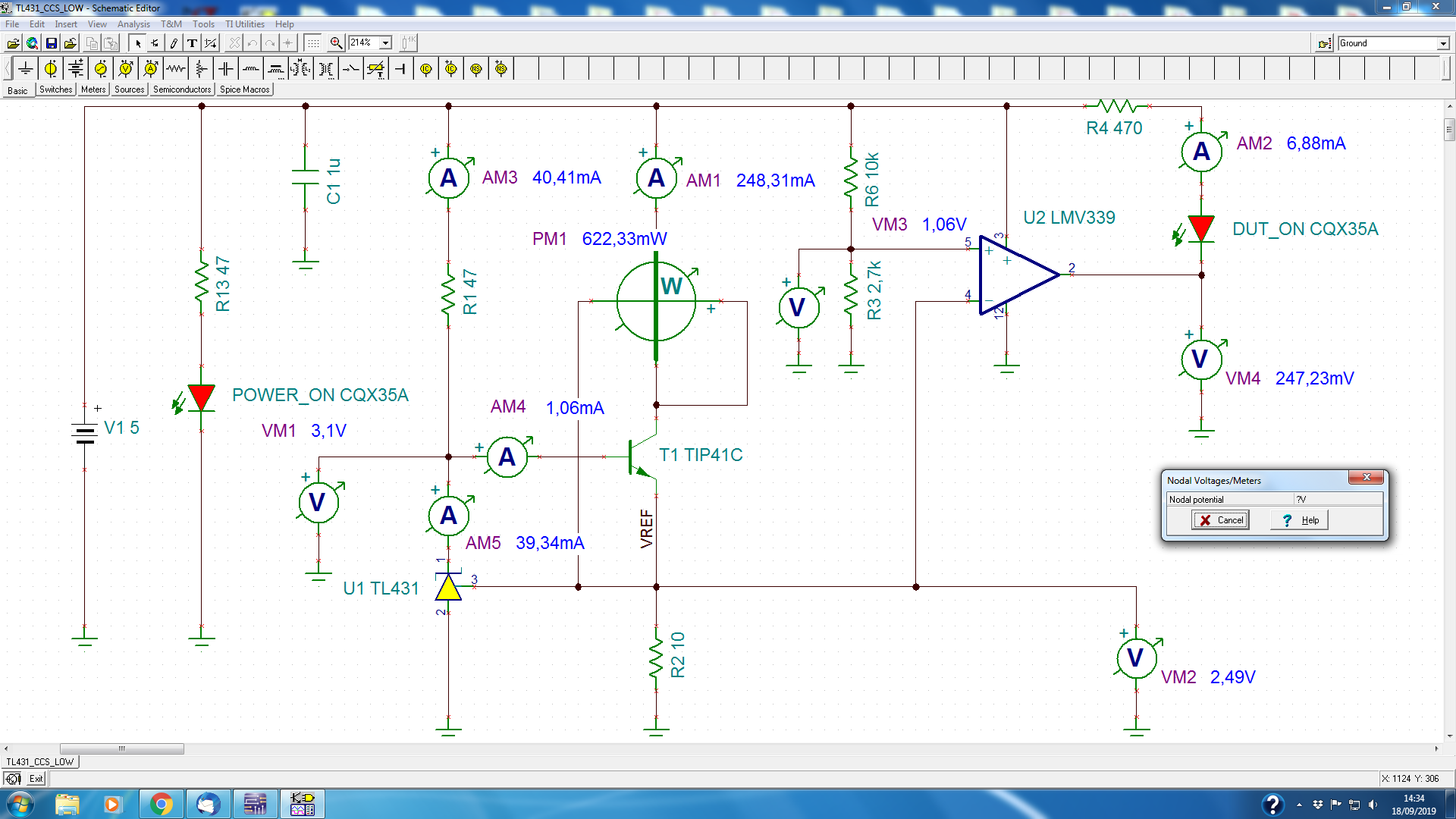
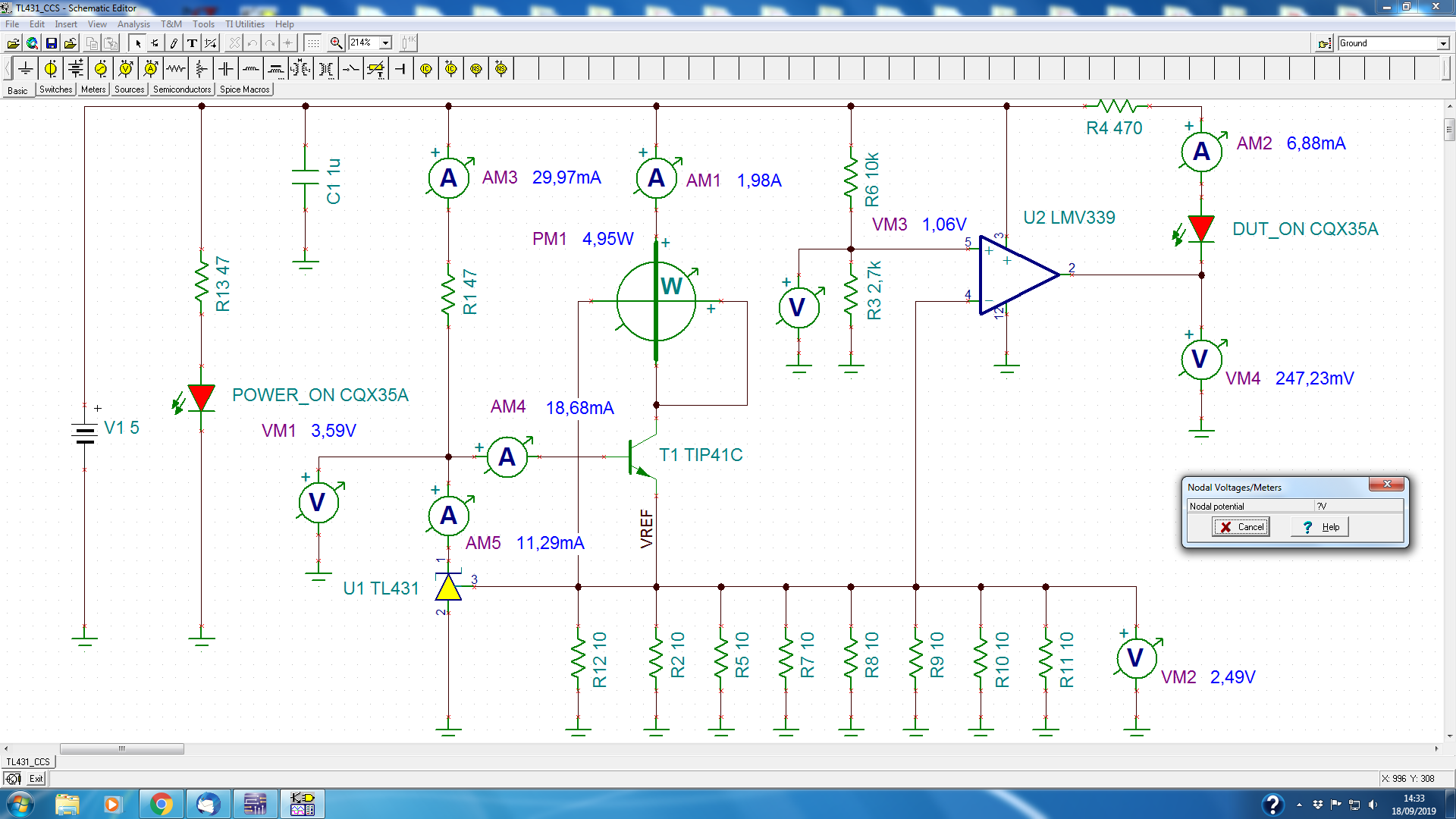
I am designing for high Energy Physics experiment a Precision Costant Current Sink. I simulated the entire circut with TINA TI using TL431 and TIP41 as BJT, the simulation was perfect it works as expected but now on the PCB (hardware) the system does not work properly the VREF is not costant when I try to vary the emitter current (adding in parallel more R 10 ohm on the emitter) and the IC (Collector current) is of course not costant I need precise current sink from 250mA to 2A in steps of 250mA. The circuiti will be used to test power cable for thermal test, the cable will be inserted from VIn (5Vdc) and BJT collector. The simulation as indicate works properly but I don't find where is the problem mybe. During simulation I used for R1 a low value because using other value the current was completely unstable. As VIn I used 5V to avoid a lot of Power dissipation on the BJT. I am sending the Tina TI Simulation files and also pictures of the schemes and pg.30 of the TI data of the Costant Current Sink applications. Thank s a lot for your help. Kind regards.

TL431_CCS.rar   Andrea Papi.
  • Hi Andrea,

    You mention that the R1 value has to be high or else the system is unstable. I would increase R1 to lower the current consumption to (2-3 mA) on the TL431 and I would add a compensation capacitor on between cathode and reference pin. This capacitor will add a type 1 pole to make the system stable.

    -Marcoo

  • Hi Marcoo,

    thanks a lot for your help, but it is exctly the contrary . I must use a low value for R1 47 ohm in Tina TI simulation. I attached the following simulation:

    TINA Ti simulation with R1 47 ohm and as you suggested I inserted a ceramic capacitor 10nF between K and VRef of th TL431 and the simulation works properly. The simulation is for the maximum step 2A. But in the the real hardware the steps are not stable because the VRef is not stable at 2.495Vdc.

    TINA Ti simulation with R1 1Kohm and as you suggested I inserted a ceramic capacitor 10nF between K and VRef of the TL431 and the simulation does not works at all it is impossible to obtain the I Max 2A.

    I am simulating with other simulator and other macro models. In the third page you will see a NI_Multisim Simulation with a Darlington BJT TIP121G the simulation work but the hardware not at all, same problem the VRef is not stable and change when IC rise.

    I suppose the problem of this linear Precision Costant Current Sink is the HFE of the BJT infact the formula for R1 is R1 = VCC / (Iout/HFE + IK (TL431)). HFE is varing with IC that is similar to IE because alfa is raffly = 1 and in particular with darlington this a big problems for their Vforward (2 Vbe).

    Hopefully I am wrong with all the simulation, if not this could be a big problem we have to trust to simulators for real analog hardware ?


    Thank for your time and I send my best regards.

    Andrea Papi- Italian National Institute of Nuclear Physics Perugia Italy.

  • Hi Andrea,

    The TL431 spice model is not an exact model that can simulate every condition. Even if the TL431 is unstable in the simulation, it will not show an incorrect voltage.You would need to run an AC simulation to see how the stability performs and not depend on the voltage output in a transient simulation. The TL431 model is very typical and will not take into account variations or corner cases that you might be experiencing.

    Im surprised it needs so much current to operate. This might mean a darlington pair will be a stronger choice than a single NPN due to the current gain.

    -Marcoo

  • Hi Marcoo,

    yes I agree with you about the TL431 macromodel, but the simulation works fine, for the TIP121G and the TL431 but the real hardware dose not works. It is completely unstable and also at the minumum current step of 250mA the voltafe reference, the TL431 Vref (Emitter of TIP121G) are 2.2V instead 2.495V. It is really strange because I am using a Darlington TIp121G with more Beta and should be better than a Power BJT as TIp141 or BD241.

    Tanks a lot for your time and help.

    I send my best regards.

    Andrea Papi.

  • Hi Andrea,

    If the VREF is 2.2V...do you have enough headroom on Vka?

    Try higher input voltages or a lower VREF device such as the TLV431 to get more head room. A 1.24V device like the TLV431 will give you an additional volt of head room.

    -Marcoo

  • Hello Marcoo,

    yes I used for VCC (VKA) 5V to 7V and for BJT TIP121G or TIP41 but VREF is not stable I am not able to have precise current steps form 250mA to 2A. I am using 1% resistors. On the board I have 15CH @ 2A max then I must  use a PS of 30A @5V. Using higher voltage means more power and more power dissipated on the BJT. The problem is the dimension of RK (R1) because it depends on Beta and Beta change with IC (IE)  I suppose the shunt TL431 does not works properly in these condition, I am not able to solve the problem for the time being.

    Thank a lot for your help.

    Best regards.
    Andrea.

  • Hi Andrea,

    Can you send me scope captures of the Vka/ Vref/ VCC voltages? Are you seeing oscillations or just not the desired output?

    -Marcoo

  • Hi Marcoo,

    you are right , yes there is an oscillation on the following points VK and VREF, in the first point I see raffly 128Khz 1.2Vpp and at VREF same frequency 128Khz and 600mVpp. I was concetraed on DC level and I tested superficially only the voltage rail that does not have any oscillation. On the card I have some filter capacitors installed, also if the TL431's data  indicated that should be stable without any cap.

    In any case I have the following ceramic capacitor on the card (still in presenze of oscillation):

    VRef = 100nF to GND;

    VK = 100nF to GND;

    10nF between VK and VREF ( you suggested to add this cap);

    I did not place capacitors on simulation because they seem of any influence, but I placed on the card for PCB design.

    The bigger oscillation is on the VK,, I am using for RK (R1) 1K. Where do I place or change value for other capacitors to tame this oscillation ?

    Thank a lot for your help.

    Best regards.
    Andrea.

  • Hi Andrea,

    From your description, oscillation is a stability issue and not a voltage head room issue. This means we have to look at that capacitors around the TL431 system.

    The capacitor on Vk that is 0.1uF is unneeded and I would highly remove it. This might be the lead culprit since it is directly on the feedback loop and it is in the unstable region. If you need a capacitor in this range, then I would use a LMV431 device. I would remove this capacitor and then add the capacitor between VKA and VREF.

    I am trying to remove all the external capacitors and see how the system reacts without them then add them back in to find the culprit. Those 2 capacitors are critical to the stability loop.

  • Hi Marcoo,

    Yesterday I tried to solve the problems now after the modifications  using C7 = 10uF , C8 = 10nF and C9 = 100nF, indicated on the scheme attached,  I have the following situation in static DC:

    VREF = 2.47V   @ Iout = 250mA

    VREF = 2.49V   @ Iout = 500mA

    VREF = 2.50V   @ Iout = 749mA

    VREF = 2.51V   @Iout = 0.98A

    VREF = 2.52V  @Iout = 1.24A

    VREF = 2.52V  @Iout = 1.49A

    VREF = 2.52V  @Iout = 1.73A

    VREF = 2.53V  @Iout = 2A

    Much better situation conform to the spec, but I was able to obtain these conditions only with the 3 caps the most important was C7 elec = 10uF between VK and VA (GND) of the TL431  TO92 case.

    In Dynamic the oscillation is tamed but does not disappear,  as you can see in attached scope screenshot I have @250mA the max oscillation of 90mVpp with frequency of 61Khz raffly, @1.25A is reduced and  @2A is quiet more current less oscillation.......

    This was the result of last evening work at the workbench, this oscillation is really strange, there are still problem with this simple circuit,

    Thanks a lot for your professional help.

    Andrea Papi

  • Hi Andrea,

    Thank you for sharing the results. The improvement due to the 10uF cap (C8 in schematic) means this circuit is unstable.This means the TL431 is in a very sensitive region where the capacitive load on the cathode will create oscillations. This circuit needs a change in the capacitor on the cathode to anode and/or a compensation network which you are doing with the cathode to ref cap. I would increase C8 if possible or eliminate it completely. When performing your tests, can you also measure Vka? I cannot see the value of Vka on your scope shots.

    Can you test this circuit without the capacitor between cathode and anode C8?

    I would highly recommend to move to a LMV431 due to the improved stability performance and lower VREF due to your limited headroom.

    -Marcoo

  • Hi Marcoo,

    good morning, It is impossible to use the circuit without C8, as I said, the oscillation is terrible 1.2Vpp@61Khz and the current steps are very unstable. Now I change C8 from 10uF to 47uF OS-Con Cap. I am sendign the result of the two different test point VEmitter (VREF TL431) and VK @ minimum stes current 250mA (this is the more sensitive step) at higher current the oscillation is in range of 10mV and it is hard to see.

    For the time being I suppose I can use the circuit after this cure, in any case I could use TL431 (I have a lot). For other project of course I will follow your hints and I'll use TLV431: I really do not understand where this strange oscillation could come, I have diffused ground and all the devices are smd but the TIP121G. I read also the Application Report Understanding Stability Boundary Condition Charts in TL431 Data and they indicate that the system is oscillation free starting from 3uF and more. Now using 47uF the oscillation is reduced the frequency is changed to 133Khz and the waform are similar on base and emitter of the TIP121G (Emitter follower). Thank you very much for your help and competence.

    Best regards.

    Andrea Papi.

  • Hi Andreas,

    A larger C8 would help but it seems you have hit the limit. Something about this circuit is inherently unstable which means you should increase C7 compensation network capacitor. Increasing or decreasing it is very specific to the system as a whole.

    Try my previous design recommendations if the TL431 stability region keeps causing large amounts of issues.

    -Marcoo

  • Hi Marcoo,

    now I have the following oscillation 29mVpp@130Khz only at mimum step, then it disappear the current steps are costant till 2A. I have the following cap: C8 between K and A = 47uF, C7 between VREF and A  = 100nF and C6 between VREF and GND (A) = 100nF The circuit is working quite well for the cable test.

    For the future I will try to use TLV431.

    Thank you very much for your help.

    Best regards.
    Andrea.