This thread has been locked.

If you have a related question, please click the "Ask a related question" button in the top right corner. The newly created question will be automatically linked to this question.

TPS7A92: TINA Simulation of NRSS pin Voltage

Part Number: TPS7A92

Hello,

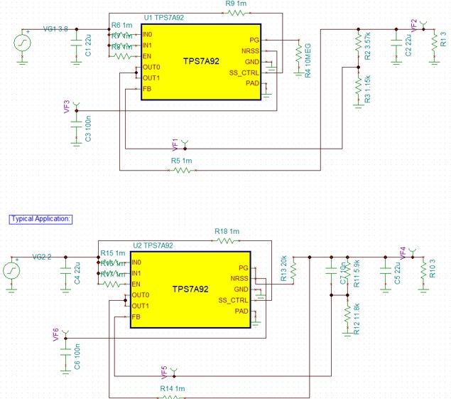
I've been trying to simulate of model of TPS7A92 in TINA, and I noticed something unusual. I've attached my simulation to this (a .jpeg and a .tsc, although I'm not sure if the attachment tool supports.tsc), and there are two cases: my design (upper) and the typical application in the TI datasheet (lower).

The simulation indicates that the voltage across the capacitor connected to the NRSS pin (VF3/VF6) perpetually increases. I think that's a bit odd, so I was wondering if you could suggest any strategies for checking my simulation setup. 

TPS7A92.TSC

  • Hey Thomas,

    It looks like when the model was created they didn't correctly show the functionality of the NR/SS pin which will only charge to 0.8V. That being said, running your TINA file the output of the LDO seems to be working correctly. Since the NR/SS pin is not intended to be connected to anything other than a capacitor you can ignore the pin's behavior in the simulation. 

    Also just taking a quick look at your schematic is there a reason you have a 10MOhm resistor from PG to GND? This will make the PG functionality unusable. There isn't a problem with doing this but it's an extra component and doesn't provide any real benefit so I figured I'd ask. 

  • Hi Thomas,

    I reviewed the simulation.
    The .TSC file was able to make it through our system, by the way.

    The NR cap charging current is modeled by a current source of 100uA.
    That was pulled from the datasheet as the typical NR cap current.

    This is not a realistic phenomenon and the simulation does not model the voltage on the NR cap properly during steady state, as you have already observed.

    Let me know if you have any other questions.

    Thanks,

    - Stephen

  • Thanks Kyle! 

    The 10 MOhm resistor was for experimentation only, I wanted to see if adding the resistor would alter the simulation model behavior.

  • Thanks Stephen! I was wondering if it was the current source.