This thread has been locked.

If you have a related question, please click the "Ask a related question" button in the top right corner. The newly created question will be automatically linked to this question.

LM74700-Q1: LM 74700-Q1 Enable Pin Blown

Part Number: LM74700-Q1

I designed a LM 74700 Q1 based circuit for connecting 58.5V battery packs in parallel to prevent forward drop from using normal diodes. I made a PCB according to the reference design given in the datasheet but did not use TVS diodes on the battery side as I was not able to find a diode in my specification. I did a test today in which three battery packs at 56v were connected in parallel using this circuit and 110A was drawn and when I checked the boards after, the Enable Pin (pin no 3) and Ground Pin(Pin number 2) were completely blown (even the pads were blown from my board) and the MOSFET(100V,260A, Rdson 3mOhm) got a drain-source shortcircuit fault. I am thinking the IC was not able to handle the current flowing through it or due to some internal fault in Enable Circuitry extra current was drawn which caused voltage spikes at my MOSFET gate which caused this source-drain short. I recently switched to these MOSFETs(Rdson - 3mohm), I was using 80V,300A,1.3mOhm ones earlier. Should i change this IC or was it some other fault?

  • Hello Abhinav,

    Could you let us know any specific instance or testing where you observed the failure.

    Possible cause would be if EN is tied to Anode, then when MOSFET turns of there could high transient voltage due to absense of TVS that could cause damage.

    Can you share the circuit schematic and test conditions when you saw the failure, along with waveforms.

    Regards,

    Kari.

  • Hello, Kari

    Unfortunately, I do not know the exact moment this failure happened as it was in a confined space and this was observed only when I took the setup out. However i can list the tests that were done that day- we tested PCBs by drawing 115 A from 3 battery packs through 3 such systems. This was supplied to a Resistor bank so I think the voltage spikes and current spikes can be ruled out for this. (connection with a linear load like a resistor should not cause a spike). The second test was with a 5Kw motor and controller as a load and a TVS diode was used on the output side (we put it directly on the DC bus of the motor controller) to protect from inductive spikes. Peak current of approximately 40A was drawn during this test. 

    I do not have the waveforms as this system was in an automobile confined space when these tests were carried out but I don't think this was due to any load issue as we have already tested this circuit for a few weeks now with only 1 IC failing in anode-cathode short. 

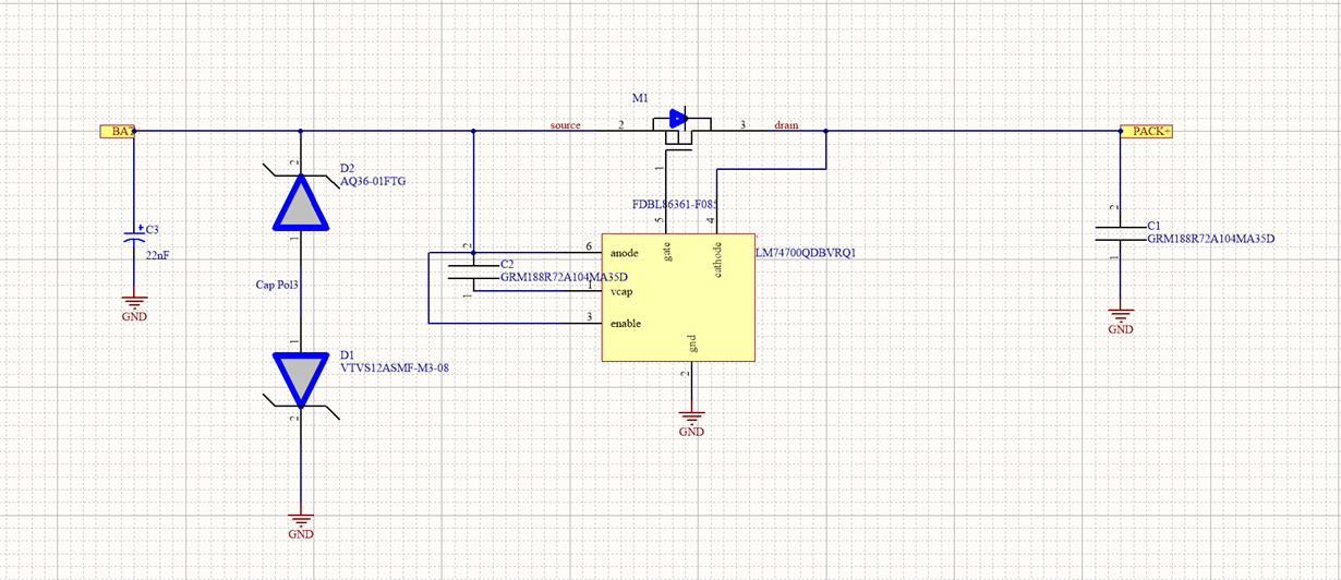
    Schematic-

    D2 was not soldered and thus there was no TV diodes on battery side but only on the pack side (cathode side of the IC). Pin number 2 and 3 were blown clean and even the pads on the board were vaporized.

  • Please reply urgently as I need to finalize whether to go ahead with this IC for my design. 

    Regards,

    Abhinav Choudhary

  • Hello Abhinav,

    With a resistor load, we do not expect any transients. However, when motor is driven with 3 batteries, did you see any back emf when breaking or any other condition where reverse current was flowing through the MOSFET and LM74700-Q1 turns off the MOSFET quickly after reverse current is detected.

    When the MOSFET turns off reverse current which flows back into battery is cut off, causes transient spikes which could have crossed maximum rating of IC pins as well as MOSFET.

    Can you try to test with TVS?

    DO you expect reverse current to flow back into battery under any motor operating conditions?

    Regards,

    Kari.

  • Yes, I have observed spikes as high as 100V after which I changed the ICs and put 7 TVS diodes (4 of 576-TPSMC62CA and 3 of 78-SMC5K60A-M3/H as i was not sure how much current would be given back) directly on the controller DC input bus. I saw 2-10A current spikes on a clampmeter through the TVS diodes and the voltage spikes also reduced to approx 60V (measured using UT890C+ multimeter). However this was observed when motor had negligible load and thus I cannot rule out voltage surges when driven on more load (in a 600kg automobile). 

    As these spikes were not observed when the motor controller was powered directly from the battery packs without LM74700, I also suspected the IC was turning off the MOS which caused the transients.

    TVS diodes were used after the observing initial surges but on the output side (directly on the motor controller)

    Honestly we dont care if some current flows back into the packs , is there a way to allow this reverse current but prevent other reverse currents (due to higher voltage on output for example)? 

    As our batteries are 58.8V max is it not safe to use these ICs even with TVS diodes?

    Regards,

    Abhinav Choudhary

  • Hello Kari,

    Please reply to my post at the earliest as I have to finalize whether to use this IC. Is the 65V rating of the IC enough for my requirement? 

    Regards,

    Abhinav

  • Hello Abhinav,

    Yes, without LM74700-Q1 reverse current would have flown back into the battery from the motor.

    With LM74700 in place, it will block reverse current and voltage on cathode side of LM74700 is going to shoot up (as motor pushes back residual energy)

    This would violate maximum ratings of MOSFETs and LM74700 as discussed earlier.

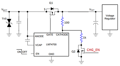
    One way to make LM74700 allow reverse current is shown in the attached circuit and discussed in this thread.

    Regards,
    Kari.

  • Hello Kari,

    I read the thread but I cant figure out how to use this in my design. First of all how did you arrive at the 1.2v figure for this 100/1k resistor bridge?

    I can only decrease this voltage difference between cathode and drain to reduce the current limit as increasing the Rds(on) would increase my losses under normal operation. Can you suggest value to limit the current at 15A using a mosfet with 2mOhm Rds(on)?

    How to use this CHG_EN to only trigger and enable (limited) reverse current when voltage at drain (output) side starts rising above a certain limit (say 60V) when braking is done on the motor. I dont want to allow this current when two packs are connected in parallel with say a voltage difference of 0.5V as this would cause heavy loads on the higher voltage pack.

    Regards,

    Abhinav

  • Hello Kari,

    When can I expect a response to my reply above? We need to finalize the design so I would appreciate it if you resolved this at the earliest.

    Regards,

    Abhinav

  • Hi,

    For 12V VIN: When Q2 is ON, ~12mA current flows through 100ohm resistor and this creates 1.2V drop across drain of MOSFET to cathode pin of IC.

    Now, reverse current detection threshold is also shifted by 1.2V, which means this will allow 1.2V/RdsON of reverse current and that is a huge current.

    Regards,
    Kari.