This thread has been locked.

If you have a related question, please click the "Ask a related question" button in the top right corner. The newly created question will be automatically linked to this question.

LM74700-Q1: motor driver bypass

Part Number: LM74700-Q1
Other Parts Discussed in Thread: DRV8704, CSD18540Q5B,

Hello TI Support,

I am working on a medical motor drive application. I am using the DRV8704 + H-Bridge (4x CSD18540Q5B) to drive a BDC motor. 
Motor is battery powered 24V nominal voltage, and can draw up to 25A 

In normal use case, the H-Bridge drives the motor for bi-directional control. so far so good.

Since this is a medical device, there is a requirement to provide a secondary path to drive the motor in ONE direction in the event of emergency. 
Conceptually, we provide direct path from Battery to the motor for uni-directional control. Note, that the system power would be switched OFF

The problem, since the motor connects to the H-Bridge and therefore the DRV8704 AOUT1/AOUT2 pins, I need isolation 

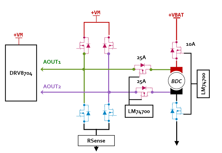
Due to system physical constraints, we can't use relays (25A). I was thinking to use the LM74700 to drive external N-CH MOSFET as per the image below

Q1) The first question, is it even possible to use LM74700 as shown above? any potential problems?

Q2)  assuming it's a non issue, is it possible to use 1x LM74700 to drive 2 Nch-FETs?

In the case of normal use case, H-Bridge is Enabled, so in one direction AOUT1 is +VM and AOUT2 is GND, and in the other direction AOUT1 is GND and AOUT2 is +VM

therefore, depending on the polarity, a reverse current must pass through the FETs. I understand that LM74700 normally blocks reverse current but can be made to allow reverse current as per another thread.

the follow up question, then

Q3) Can the LM74700 be used to drive the 2-Nch FETs in this configuration? How would one connect Anode/Cathode ? 

Any recommendation / solution to the above is appreciated. 

Thank you 
AJ

  • Hi,

    Let me look into this question by Monday 9/30 and get back.

    Regards,

    Kari.

  • Hi

    Normal use case:

    In one direction, where top left MOSFET and bottom right MOSFET of H-Bridge are controlled, LM4700 on 25A path (RED color) would have power and turn on its MOSFET to allow current. However, second 25A LM74700 (blue) need to allow reverse current and this one does not have power, MOSFET would be off and its body diode will block reverse current.

    In other direction, RED LM74700 needs to allow reverse current and will not have power to function and BLUE LM74700 turns on the MOSFET as it has power (VM+).

    The main issue here is how to keep two LM74700 powered in both direction of BDC drive. To allow reverse current, power needs to be available and if power is available by some means, we can make LM74700 to allow reverse current.

    Do we have any negative supply available in this design?

    Regards,

    Kari.

  • Hello Kari,

    Thank you for getting back to me.

    Unfortunately, we only have positive supply.

    You are correct, in one direction there would be power but not in the reverse direction and hence my question.

    Thinking more about it, I suppose we can move the Lm74700 and drive NCH FET before the H-bridge. In normal operation the lm74700 drives the high side NCH FET and provides power to the h-bridge. In case of emergency the Lm74700 can be disabled to switch OFF +VM to the Hbridge. The body diode would also block path from the motor through the H-bridge FETs

    Now I would only need a way to *disconnect" the drv8704 from the Hbridge in bypass mode when there is a direct connection to the battery.

    I believe AOUT1/2 are sense lines only, so a low current HV "switch" will do. The same for AxHS/AxLS except those are limited to 400mA max sink current. 

    Can you please advise if the above would work. Any issues with this approach?

    I'm not particularly married to the lm74700, so if there is a better part suited for the job then please feel free to suggest.

    B) do you have a TI part that can be used for switching  AxHS/AxLS, AOUTx and AISENx lines and  disconnect drv8704?

    Thanks

    AJ 

  • Hi 

    I am looking at your response and will get back tomorrow or if possible today.

    Let us know if you are looking for speedy response here.

    Regards,
    Kari.

  • Hello Kari, thank you for the note. 
    No immediate rush, but would like to finalize on the circuit to finish off pcb layout.

    Thanks

  • Hello,

    Could you let us know which pins of DRV8704 needs protection other than AOUT1 and AOUT2?

    Regards,

    Kari.

  • hello Kari,


    In case of emergency, there should be a separate path to drive the motor and bypass the H-bridge.
    Only AOUT1/AOUT2 pins remain connected to the motor terminals and require protection / isolation.

    thanks
    AJ

  • Hello,

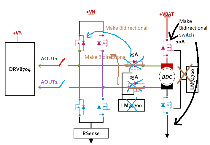
    I have made changes to the proposed scheme.

    Basic idea is to make connection from DRV8704 to bridge using relay (these are low current signal paths), for AOUT1 and AOUT2.

    And move the blocking diode circuit of LM74700 to towards MOSFETs connecting to VM node as shown in attached figure.

    Top MOSFET switches connecting to VM are made bi-directional and will always have power to control LM74700.

    During normal operation battery is disconnected by bi-directional switch, and both direction control works because of the bidirectional switches on top of VM node. 

    When battery is only present, no power on VM, then AOUT1 and AOUT2 are protected and no leakage to VM or GND.

    Let us know if this solution works for you.

    Regards,

    Kari.

  • Hello Kari,

    Thank you for getting back to us on this.

    I believe this should work, I wasn't 100% sure about AOUTx current being low current signal path. The datasheet is not clear.

    Now for bi-directional side switches, and if I understand correctly, 1x LM74700 can be used to drive 2x FETs in back-to-back configurations. 

    Can you please confirm?

    Cheers,
    AJ

  • Hello AJ,

    LM74700-Q1 can not drive two back-back  MOSFETs.

    One MOSFET still needs to b driven by MOTOR control.

    Blocking MOSFET will be driven by LM74700.

    Regards,

    Kari.

  • Hello Kari,

    I apologize for the late reply (was away) and thank you for the confirmation!

    Cheers,
    AJ