This thread has been locked.

If you have a related question, please click the "Ask a related question" button in the top right corner. The newly created question will be automatically linked to this question.

TPS7A25: TPS7A25: Datasheet serious error

Part Number: TPS7A25

I use TPS7A25 in my power circuit. And noticed some strangeness, picked up dividing resistors in feedback to get 3.3V.

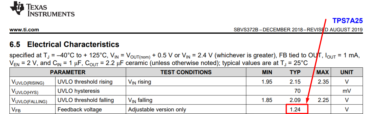
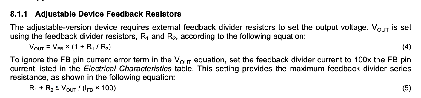
According to the datasheet formula Vout = 1.24V*(1+(R1/R2)) I chose 3.3M and 2M to get 3.28 V output. But when I soldered the circuit, I got the output about 4.05V

Then check the output voltage on VB pin - it is 1.54V, which, when substituted into the formula, just gives 4.08V, which, taking into account the accuracy of the resistors, is close to the measured.

Then checked on the other two boards and the output voltage was 3.98V and 4.02V and the voltage on the VB is 1.54V

I assumed that in the datasheet a typo of 1.24V instead of 1.54V and picked up a new pair of 1.2M and 1.1M, which gave an output voltage of 3.15V (1.54*(1+(1.2/1.1))=3.22V).

Please tell me, is this really a mistake in the datasheet?

  • Hi Ivan,

    The problem is the leakage current into the FB pin. The datasheet recommends that the feedback resistor divider be sized such that this does not impact the regulation voltage:

    This is equation 5 shown above. If you want to have 3.3VOUT and minimize the leakage due to the feedback resistors, you might want to switch to the fixed output voltage version. Right now it is sampling (TPS7A2533). 

    If you wish to keep the adjustable version, the series resistance should be less than or equal to 110K.

    I hope this answers your question.

  • Ok, I will test tomorrow with 10x lower nominals...

    But.

    From (R1+R2)<=Vout/(Ifb*100) => (R1+R2)<=3.3/(10nA*100) = 3 300 000 Ohm

    My pair 1.2M and 1.1M  meets this requirement

    In datasheet there is an example for 5V :) with 5 MOhm

  • Hi Ivan,

    One other thing to consider is those very high-value resistors demand a very clean PCB. If there is any contamination or solder-flux underneath, this can cause an additional leakage path which would change the effective resistance. 

    I hope this helps.

    Regards,