This thread has been locked.

If you have a related question, please click the "Ask a related question" button in the top right corner. The newly created question will be automatically linked to this question.

LM46002: Testing Margin of Stability and Inductor Current Limit in Buck Converters

Part Number: LM46002

I am using a LM46002 as a standard buck converter and another LM46002 in inverting configuration.  I am also using a LM2676 with fixed 5V output in an application that goes right up 3A limit.  Is there an app note for measuring marginal stability, inductor current headroom, and any other parameters of the power supply?  I'm looking for simple tests to verify there is nothing on edge that may cause problems in the future.

Everything is working great.  I even can add a few hundred mA load to my LM2676-based 5V supply without hitting current limit.  But I would like to see if there's anything marginal in my power supplies.  

  • Charles,

    For stability you can run a bode plot to view phase and gain margin. Check the phase and gain margin values but to evaluate robustness, check that variations in gain/phase crossover frequency will also be stable. For example if your phase is 60 degrees at the gain crossover, your stability will probably be fine. But if the phase drops to 10 degrees (for example) very close to the crossover, the system may have a 10 degree phase margin if component variations change the crossover frequency by that much.

    As for high-current robustness, the part will operate up to the current rating and a bit beyond depending on the current limit and the inductor ripple. The biggest issue to look out for is the thermals, not so much the current itself. Check to ensure the part does not exceed the max temp rating at max ambient temp at max power out.

    -Sam

  • Samuel Jaffe said:
    Check the phase and gain margin values but to evaluate robustness, check that variations in gain/phase crossover frequency will also be stable.

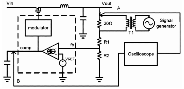
    What characteristics should I look for in a transformer to inject a signal into the feedback path?

  • Charles,

    You can find guidelines in app notes such as this one.

    -Sam

  • Samuel Jaffe said:

    For stability you can run a bode plot to view phase and gain margin. Check the phase and gain margin values but to evaluate robustness, check that variations in gain/phase crossover frequency will also be stable. For example if your phase is 60 degrees at the gain crossover, your stability will probably be fine. But if the phase drops to 10 degrees (for example) very close to the crossover, the system may have a 10 degree phase margin if component variations change the crossover frequency by that much.

    I found the point of where the voltage on the sides of the test resistor was a function of load.  

    Load Unity Gain Frequency
    0 20.5Hz
    15mA 810Hz
    30mA 1,403Hz
    1.5A 4,080Hz

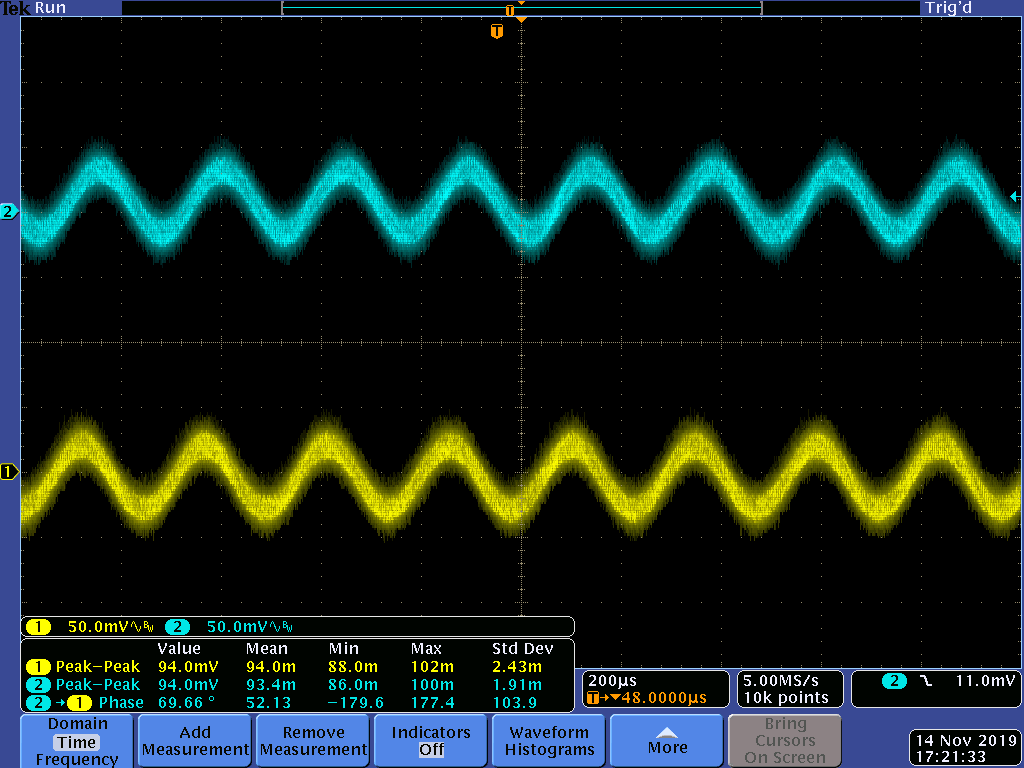
    Waveforms with 1.5A load:

    Across all frequencies and all loads, the AC voltage on the output lagged the voltage on the other side of the test resistor by around 30 degrees.  It's hard to estimate the amount of phase difference, but that's what I got comparing the time between peaks to the period.  

    Does this sound normal?

  • Charles,

    Yes this sounds normal.

    -Sam

  • Thanks for confirming what I'm seeing is normal.

    In this testing I injected a signal just as suggested in the app note you recommended.  

    How would I do this same test on an LM46002 in the inverting mode?

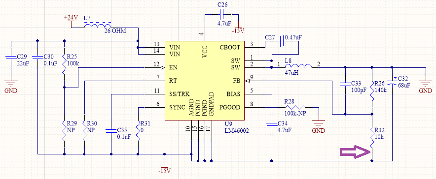
    My board has an LM46002 configured for +15V and -15V.  Here is the schematic for -15V.  The purple arrow shows where I broke the loop and added 33 ohm resistor.

    The trouble is the amplitudes are the same (unity gain) across various frequencies and loads, unlike the tests I did on the +15V supply.  Am I breaking the loop in the wrong place?

  • Charles,

    Break the loop on the top feedback network like in the non-inverting test.

    -Sam

  • Samuel Jaffe said:

    Break the loop on the top feedback network like in the non-inverting test.

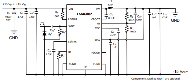
    In inverting mode the top of the feedback network is ground.  (This Figure 1 from the Inverting Applications App Note.)

    The procedure calls for measuring the signal referenced to ground.

  • Charles,

    Please refer to the app note SNVA856, figure 6.

    -Sam

  • Samuel Jaffe said:

    Please refer to the app note SNVA856, figure 6.

    I see, I need to float the scope and measure the signals referenced to the negative supply output.

    Thank you for your help with this question.