This thread has been locked.

If you have a related question, please click the "Ask a related question" button in the top right corner. The newly created question will be automatically linked to this question.

LM25085: LM25085 output voltage drop to zero for 250~300ms when output current is 8A

Part Number: LM25085

Hello

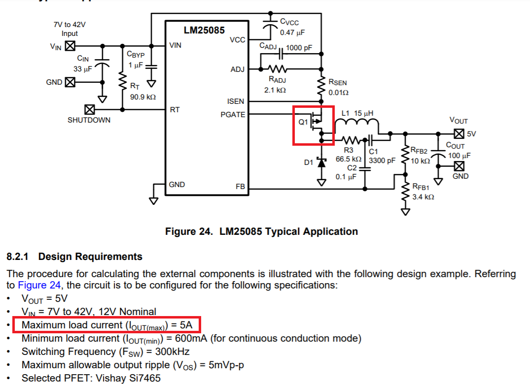
A customer said if the LM25085 output current exceeded 5A, the output voltage will drop. i will get more detailed information to you, but I have a question about its maximum output current if it's depended on the MOSFET Q1 in the picture from the datasheet., instead of the constant 5A. The output voltage wave is as following.

let's discuss the phenomenon.Background :VOUT=8.4V, VIN=25V, electronic load =8A

1.LM25085 output 8.4V drop to 0 for 250~300ms when input voltage is 25V.

2.The output current is 8A. This phenomenon appears after it works normally for 40s.

3.The output current is 5A. This phenomenon appears after it works normally for 3 mins.

4.It works normal if its output current is lower than 4A.
I think 8A triggers current limitation to some degree. I have given some advice to customers for examinations and got results in bracket.
1.Is VIN drops to zero for 250~300ms.(NO)
2.Is Q1 Vgs>3V for full conduction.Q1 is AO4421(YES)
3.Increase RADJ to 3.3kΩ for higher current limitation.(no use)
4.Change RSEN package from 1206 to 2512.(no use)
5.Value of RSEN increase with power dissipation.(RSEN =0, no use)
6.L1 is saturated in 8A.(unverified)
7.8A simulated from electronic load, current wave.(unverified)
What is the problem?

  • Qun,

    The LM25085 is a buck controller. This means the maximum output current is dependent on the current capability of the FET and the LM25085's ability to drive the FET. The drive strength of the LM25085 is strong enough to conservatively drive a FET for a solution of as high as 10A.

    Section 8.2.1 as you've highlighted states the design requirements for a typical circuit using this part. These are specifications that a customer may have for a system. The design requirements are what we use to select the components. The specs for this example state a max current of 5A so the example is designed for a max current of 5A.

    The design can be modified to allow higher current. This can be done by selecting a higher-current-rated FET and by adjusting the current sense resistor and/or the components leading to the ADJ pin.

    You can refer to the LM25085 datasheet for more information.

    -Sam

  • Qun,

    Please do not change the title and original post content after you've received a reply. This takes away the context for the reply. If you have more information to add, please post a reply so we can carry on the conversation. Or if it's a new question, please post a new thread.

    To answer your new questions:

    It sounds like the device is hitting over-temperature protection. Please check if the device is getting very hot. If so, you may need to change the layout to improve the thermal performance. Share the layout and I can give suggestions.

    -Sam

  • I'm sorry for my behaviors.

    Thank you for helping. The problem was identified. I told the customer using a fan to speed up heat dissipation and it works. The output voltage can be maintained.

     It seems occupied too much space if the customer follow the layout in the datasheet because them wish to use space as less as possible . Maybe you can share some advice on their layout after they upload the layout.

  • Qun,

    Yes I can provide advice for the layout but it will probably be the same advise as in the datasheet. More space means more heat dissipation which means better thermal performance. But I will take a look when it is uploaded.

    Thank you,

    -Sam

  • Hi, Sam

    Here is the layout, maybe it's hard for advice ...

  • Qun,

    The LM25085 has an exposed pad / thermal pad / die-attach pad on the bottom of the IC. This should connect to the ground plane and should have lots of copper area to spread the heat. See the layout example in the datasheet. The layout you've shared connects to very little copper so the heat doesn't have much to help it spread away from the IC. This causes the IC to heat up at higher output power which cause cause the IC to turn off when it hits thermal shutdown.

    -Sam