This thread has been locked.

If you have a related question, please click the "Ask a related question" button in the top right corner. The newly created question will be automatically linked to this question.

LM5104: Driving parallel mosfets

Part Number: LM5104
Other Parts Discussed in Thread: TIDA-00364

Hi,

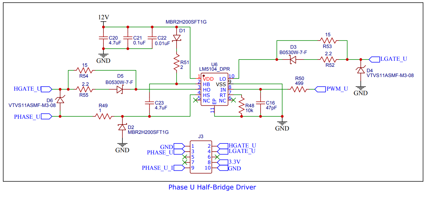
I would like to use three LM5104's to drive mosfets in parallel for a three-phase inverter.

If using individual gate resistors, is it suitable or would there be other precautions. For example is it possible the adaptive delay circuitry would have unintended side effects with parallel mosfets?

Thanks,

Andrew

  • Hello Andrew,

    Thank you for the interest in the LM5104. I would not suggest, or have we tested, half-bridge drivers connected in parallel. Differences in propagation delays, especially with programmable dead times, can lead to timing conflicts which has the potential to cause stess especially on the high side floating driver.

    If you need higher drive current and want to connect several MOSFETs in parallel, I would suggest using a BJT buffer (NPN/PNP) on the driver outputs for higher drive current, then connect separate gate resistors to each MOSFET gate. Below is a reference design link showing driving parallel IGBT's with BJT buffers. The BJT buffer and gate connection recommendation is what I suggest in your application.

    http://www.ti.com/lit/ug/tiduc70a/tiduc70a.pdf

    Confirm if this addresses your questions by pushing the green button, or you can post additional questions on this thread.

    Regards,

  • Hi Richard,

    Sorry for the ambiguity in my post. To clarify, it is the mosfets placed in parallel, not the gate drivers. There is only one LM5104 for each of the three half-bridges in the three-phase bridge. The usage is the same as in TIDA-00364, but different drivers.

  • Here is my anticipated usage

  • Hello Andrew,

    Thank you for clarifying your intended method of paralleling the MOSFETs. With a single driver driving several parallel FETs we always suggest using separate gate drive resistors to each FET. There should not be significant timing differences in the parallel FET's, any difference would be from variation in gate charge. If there are concerns about some small difference in the MOSFET switching, the LM5104 allows to set additional delay time with the RT pin which I would suggest in this case.

    Confirm if this addresses your concerns by pushing the green button, or you can ask additional questions on this thread.

    Regards,

  • Hi Richard,

    Thank you, good to hear. Can you see no issues then with my usage above? Please ignore the current sensor.

  • Hello Andrew,

    The connection and the paralleling of the MOSFET's looks OK. The one comment I have is regarding the HB capacitance and VDD capacitance.

    I see that 3 of the MOSFETs have fairly high gate charge of 3x 122nC or 366nC. The 4.7uF boot capacitance will result in low ripple from charging the MOSFET Qg. We usually recommend that the VDD capacitance is 10x the boot capacitance to allow charging the boot capacitance without a large voltage drop on the VDD capacitor. The VDD capacitance is also 4.7uF, so I would recommend increasing the VDD capacitance.

    Confirn if this addresses your question by selecting the green button, or you can post additional questions on this thread.

  • Thank you for catching that, I see that was written in the datasheet.

    Thank you for the help.