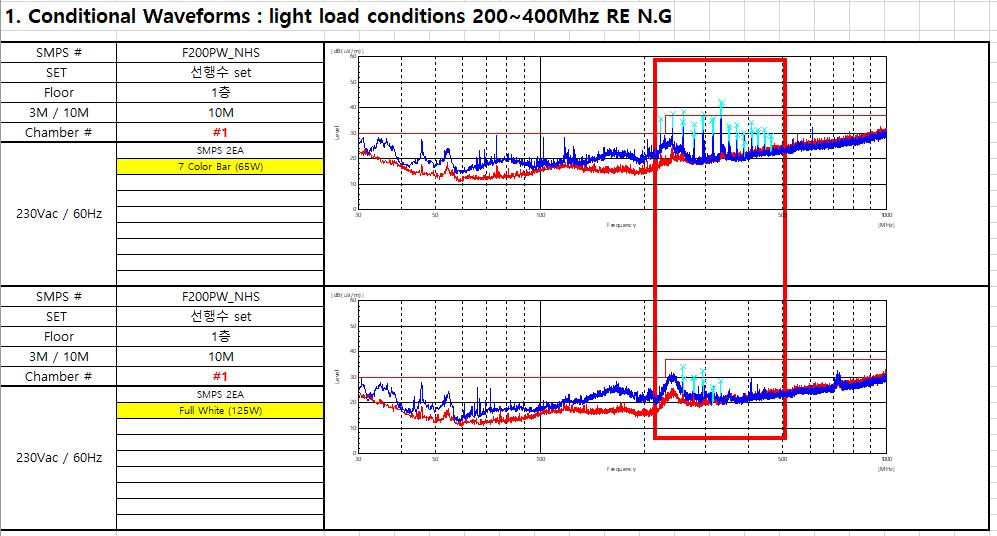
This thread has been locked.

If you have a related question, please click the "Ask a related question" button in the top right corner. The newly created question will be automatically linked to this question.

TPS2412: Inquiry about RC filter of VDD.

Part Number: TPS2412

Hi TI team.

My customer have EMI issue of TPS2412.

RC filter (10ohm and 0.01uF) of Vdd are recommended for the datasheet.

But we need to apply 47 ohms to get 5 dB improvement. 10 ohms has no effect.

Changed circuit was applied as below, not the usual RC filter. (The value of the capacitor is also large.)

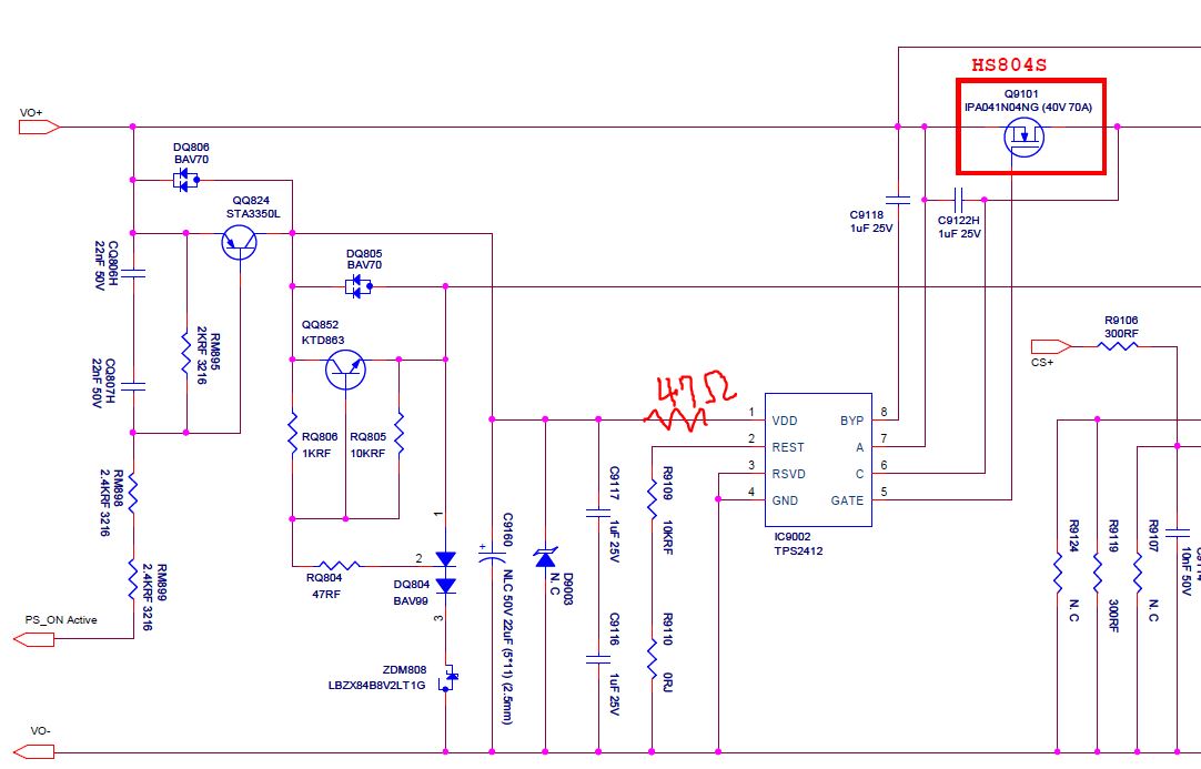
Will there be side effects on 47 ohms and modified circuits?

Please check if there is a problem in the circuit.

Thanks.

  • Hello Downey,

    47 ohm and two 1uF in series is not a problem.

    is there any reason to use two 1uF in series? unless voltage rating is a concern, two in series will double the ESR which may not be good for EMI.

    Regards,

    Kari.

  • Hi Kari,

    Thank you for your answer.

    EMI data before and after applying 47ohm is as follows.

    Please answer the questions below.

    1. Is switching occurring inside TPS2412? 

    2. What do you think is causing noise in TPS2312?

    3. Why improve EMI when applying 47 ohms?

    This is a difficult question, but I have a customer request. please answer about my question.

    Thanks.

  • Hi,

    EMI spike at 200MHz is due to the charge pump switching, every switching cycle of charge pump it takes pulse current from Vdd.

    Adding 47ohm and decoupling capacitor helps to reduce the EMI.


    Placing the decouping capacitor closer to the IC will reduce the loop of the spike current drawn by the internal charge pump of the IC.

    At 200MHz, placing a small value of capacitor 100nF (high frequency capacitor) or if possible, better EMI, one 10nF and one 100nF high frequency bypass capacitor would be best.


    Regards,

    Kari

  • Kari

    Thank you so much!!

  • Hi Kari,

    The customer asked some additional questions.

    As shown in the attached test result, the noise is high at light load. (30W - noise is high, 60W - noise is low)

    1. What causes noise at light load?

    2. What is the current at the point where switching noise does not occur?

    3. Please let me know if there is a way to check the switching phenomenon outside the IC. (using scope)

    Thanks

  • Hello Downey,

    I see a email communication regarding this very same issue and have responded over email in detail on the root cause of EMI margin issue at light load.

    At light load conditions, if minimum load current (for example 10mA as mentioned in datasheet), gate will oscillate ON/OFF continuously. This is due to the action of  linear regulation amplifier trying to maintain a 10mV across IN-OUT through gate of the MOSFET. At light load, to meet 10mV regulation, RdsON has to be 10mV / I_Load. At load current of 1mA, RdsON = 10mV / 1mA = 10ohm and to achieve such high value of RdsON, gate-source voltage has to be very close to gate threshold voltage. Attached gate-source voltage vs RdsON characteristics of MOSFET Si7336ADP. To achieve 10ohm Vgs has to be very close to Vth (3V). 10mV regulation will have stability issues if sufficient load current is not maintained.

    Regards,
    Kari.