Hi Team,
Please help me with the following thing:
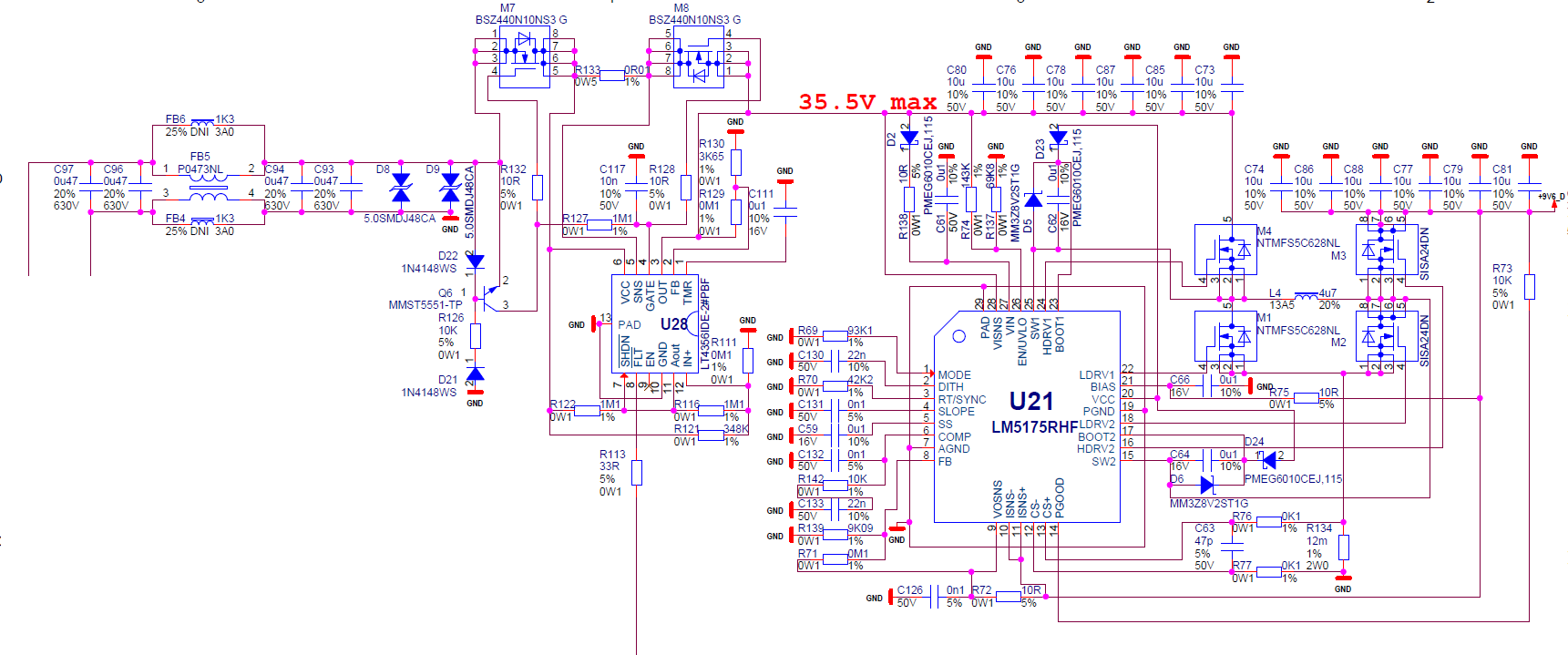
My customer made a design with LM5175 (Please see attached initial schematic) and now trying to bring it up.
Here are the problems:
- During steady state input LM5175 sometimes switches to a very strange working mode with resonant waveforms, voltages similar to those described here: https://e2e.ti.com/support/power-management/f/196/t/853891?tisearch=e2e-sitesearch&keymatch=lm5175. Being configured in DCM the device is always in that mode, and sometimes unable to stabilize the output voltage at all. After all of the schematic corrections (see below), the device starts from the twice lower frequency than programmed by RT/SYNC and then switches to normal while I’m increasing the input voltage. The COMP voltage remains within a range as in the Quickstart Tool Excel table and it is steady.
- Start-up from low voltage input (~6.45V) is not smooth and steady but rather oscillating. Sometimes for 20ms, sometimes for seconds. I blamed a protection circuit (U28) initially, but direct power supply connection to LM5175 input did not change a thing. Tried adding electrolytic caps (470uF) to both input and output - this reduced the symptoms of both problems but did not eliminate them at all. Moreover, I tried to connect to the same protection circuit MAX20048 and LT8390A EVBs and both start flawlessly.
They deliberately did not use electrolytic capacitors for high temperature longevity reasons. This affected the load transient response, but I’m OK with that, since afterwards I use DC/DC converters to make 4.0V and 5.0V from 9.6V.
So they made the following modifications to the initial schematic:
- Added 2.2uF to U21.VCC
- Added 1uF to U28.VCC
- Shorted U21.DITH to GND
- The R69 from 93.1K connected to GND changed to 0Ohm to VCC, also tried 200K to GND, seems to be the same as 0Ohm to VCC, CCM, no hiccup.
- Re-calculated compensation network with the help of Quickstart Tool Excel table to 1.27K/33nF/47pF instead of original 10K/22nF/100pF.
Seems that they missing something very basic with this design.
Thanks,
Shlomi