This thread has been locked.

If you have a related question, please click the "Ask a related question" button in the top right corner. The newly created question will be automatically linked to this question.

BQ76PL455EVM: BQ76PL455EVM

Part Number: BQ76PL455EVM
Other Parts Discussed in Thread: BQ76PL455-Q1, BQ76PL455A-Q1, BQ76PL455A

Hello,

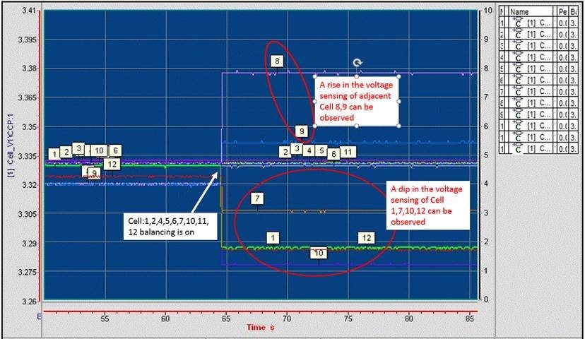
I am doing cell balancing algorithm validation at our company. During the validation, it is observed that there is a instantaneous deep in the cell voltage whose cell balancing is turned ON and there is rise in the cell voltage of the adjacent cells. For e.g. if the balancing of 10th cell is ON there is a dip in the cell 10th voltage and rise in cell 8th and cell 9th voltages. As per the available documents on bq76pl455-q1 slave board, it is specified that there'll be a dip and little rise in the cell voltage, but that is not quantified and the reason is also not given. Need to find the root cause of this issue. Screenshot is attached.  
Regards,

Saurabh Shah

  • Hi Saurabh,

    Part of this is when you turn cell balancing on, there is an IR drop on the cable that connects the battery to the BQ76PL455A-Q1 board. When balancing is enabled, the current will increase and therefore cause a larger IR drop that can be seen by the VSENSE pins. Other part is due to the battery characteristics itself such as it's internal resistance. To get an accurate voltage reading you can stop balancing when you want to monitor the cells voltage and then resume balancing. 

    Best regards,

    Leslie

  • Hi Leslie,

    Thank you for your prompt reply. It is justified that there's voltage drop seen by the VSENSE pins. But I couldn't understand why there's rise in the cell voltages whose balancing is off. Please refer the attached screen shot for reference.

    Best regards,

    Saurabh 

  • Hi Saurabh, 

    When balancing for example cell 3, the IR drop on the cable that connect to the battery cell 3 + side will be seen by cell 4 - side, and the IR drop on the cable that connects to the battery cell 3 - side will be seen by cell 2 + side. Hence, the voltage sensed by these adjacent cells will be also impacted. 

    Best regards,

    Leslie

  • Hi Saurabh, 

    Are you using the bq76pl455A EVM or a custom board you designed? 

    Can you make sure you don't have resistor ladder connected to the cells?

    Regards,

    Leslie

  • Hi Leslie,

    I am using bq76pl455A EVM for testing. There's no resistor ladder connected to the cells. 

    Can you help me to get the reason of why there's rise in voltage in adjacent cells? This rise is not observed in all cells as you can see in the screenshot.

    Thanks & regards,

    Saurabh

  • Hi Saurabh,

    I looked into your plot in more detail. The explanation I provided to you is still valid for cases when you turn balancing ON on a cell, but cell balancing is OFF for the adjacent cells (the cell above and the cell below). For cases when you have consecutive cells with balancing ON (for example cells 10, 11 and 12 in the plot you provided) you need to look at the circuit in a little more detail to see the path that the balancing current takes. I have an example below to explain what you are seeing, but my example is an ideal case. The amount of IR drop you see depends on the resistance of your cable and take into account that each cable has different IR drop so you won't see the same drop/rise on the voltage sensed for all cells.

    Let's take for example the case of turning balancing ON for cells 10, 11 and 12, and let's assume all cables are matched to have the same impedance. When you turn on cells balancing for cells 10, 11 and 12, the balancing current will flow from cell 12 "+" side, into cell 10 "-" side (through the external FETs).

    • VSENSE12 will see a voltage drop due to the IR drop of the cable that connects cell 12 "+" side  when balancing current is flowing
    • VSENSE11 won't have a drop or rise since the balancing current is not flowing in or out of cell 11 "+" side nor cell 11 "-" side.
    • VSENSE10 will see a voltage drop due to the IR drop of the cable that connects cell 10 "-" side  when balancing current is flowing
    • VSENSE9 will see a voltage rise because balancing current is flowing into cell 10 "-" side which is the same as cell 9 "+" side

    If this amount of drop/rise in voltage reading is not acceptable, I recommend you take voltage measurements only when cell balancing is off. To decrease the amount of voltage drop/rise, you can test with cables that have lower resistance so your IR drop decreases.

    Best regards,

    Leslie

  • Hi Leslie,

    Thank you for the reply. Now it is justified why there's a rise voltage of cell 9. Here's my understanding, please correct me if I go wrong,

    • As you said there's no balancing current flowing in or out of cell 11 "+" side or cell 11 "-" side. I have come to the conclusion that the current flowing in the cell 11 "+" and cell 11 "-" side will cancel out each other and the effective dip in cell 11 voltage will be minimized.
    • VSENSE9 will see a voltage rise because balancing current is flowing into cell 10 "-" side which is the same as cell 9 "+" side. This is because the effective current flowing through cell 9 "+" side will be (Isense-Ibal) where Isense is the sense current and Ibal is the balancing current. So if I apply KVL to that loop, the voltage at the VSENSE9 will be "VSENSE9=V9-(Isense-Ibal)*R" (wire resistance), where V9 is the voltage of cell 9. As Ibal is greater that Isense, the effective voltage will be high at VSENSE9 pin and there will be a rise in VSENSE9.

    Another thing I want to ask is, if I do balancing during charging of the battery, where charging current is of the order 100-200 Amps, will there be a problem in the PCB (like damage to the MOSFET switch used for balancing, damage to the cell monitoring IC, etc) because of such high current?

    Thanks & regards,

    Saurabh Shah

  • HI Saurabh,

    Your 1st statement is correct. If there no cell balancing then Isense will cancel out each other. Assuming Isense and cable impedance is identical.

    If I understand your 2nd point correctly then you are correct on 2nd point too.

    Remember, you are limiting the balancing current with balancing resistors.

    You have to watch out for thermal of PCB and also make sure you have proper power rating components. Check the "W".

    roger

  • Hi Roger,

     Actually, if you go through the thread, you'll see that balancing of 11th cell is ON. I want to know whether (Ibal+Isense) will cancel out in cell 11"+" cable?

    Thanks & regards,

    Saurabh Shah

  • HI shah

    Leslie responded this.

    VSENSE11 won't have a drop or rise since the balancing current is not flowing in or out of cell 11 "+" side nor cell 11 "-" side. Because
    Cell balance 10 and 12 are ON.

    Roger

  • Hi shah

    My answer is assuming same cell voltage and balancing current.

    There could be some current to Cell 11+ if cell 11 balancing is higher.

    You have draw current path with cell 12, 11 and 10 ON.

    current path is cell 12 wire -> cell 12 balancing FET-> cell 11 balancing FET -> cell 10 balancing FET-> cell 10- wire.

    Roger

  • Hi Roger,

    Thank you for the explanation. I was able to verify the same in simulation in MATLAB. 

    Can you please answer to the query that I've asked in this thread regarding charging of the Li-ion battery at high current along with the balancing ON?

    Best regards,

    Saurabh

  • Hi Saurabh,

    Roger replied to your question on this thread on his post from December 12.

    Best regards,

    Leslie

  • Hi Saurabh,

    I will close this thread and please let us know if you have more questions.

    thanks

    Roger

  • Hi Roger,

    Thank you for the replies.

    Regards,

    Saurabh