This thread has been locked.

If you have a related question, please click the "Ask a related question" button in the top right corner. The newly created question will be automatically linked to this question.

WEBENCH® Tools/LM5122: controller over temperature warning

Part Number: LM5122
Other Parts Discussed in Thread: CSD18509Q5B, CSD18503Q5A

Tool/software: WEBENCH® Design Tools

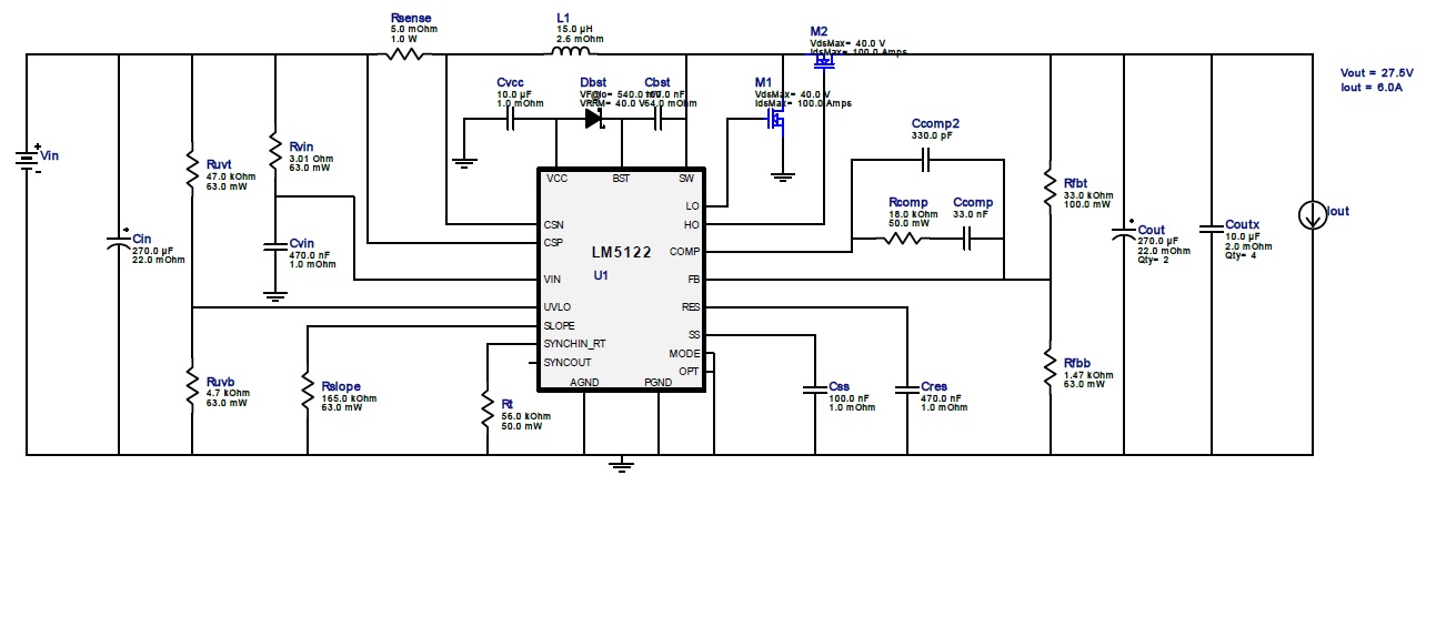
My initial design based on an LM5122 had the following specifications: Vin [18V-22V] Vout 24V 8A.

The specifications have changed, but I would like reusing the same PCB preferably keeping the same inductor: Vin[16V - 28V] Vout 28V 8A.

I run WEBENCH again with the new specifications, the switching frequency has dropped from 160kHz down to 90kHz and the inductor has been increased from 15uH to 33uH and is not compatible with my existing PCB. I set the switching frequency to 160kHz in the design option in order to keep the 15uH inductor but I now get warning message about the maximum temperature reached by the LM5122.

The warning clears if I reduce the maximum load to 7A, which would be good enough for me, but I now think there is a risk with the LM5122 and I am not sure my design is safe.

It seems the overheating of the LM5122 is caused by the increase of the input voltage but I don't know how to evaluate the maximum power dissipated in the LM5122.

I evaluated gate drive loss to ~0.22W (gate charge 140nC high side switch, 25nC low side switch).

Would it be possible to help me evaluating if my modified design is safe and if not what needs modifying. Thanks.

M1 CSD18503Q5A, M2 CSD18509Q5B

  • Hi Gilles,

    Thanks for reaching out with your questions and for using the LM5122.

    To help with the calculations for the power train components please use the LM25122 quick-start calculator. Some functionality as the LM5122 but lower higher input voltage range. This will allow you to see the changes that need to be made while staying at the same switching frequency. Regarding the WEBENCH error it is probably the MOSFET temperature that is triggering it. If you lower the ambient temperature it should help with the simulation.

    Regarding the safety it of the design, I think it is right on the edge of being a dual phase design. A single phase design should work but thermal management will need to be considered. A dual phase example is the LM5122 2 phase EVM. This is a good reference.

    www.ti.com/.../lm5122evm-2ph

    Let me know if you have any questions.

    Thanks,

    Garrett

  • Hi Garret,

    Thanks for your answer and the spreadsheet for dimensioning the LM5122.

    I noticed in the spreadsheet that the maximum gate charging current should be less than 50mA.

    - Should I take margin on this limit? If yes, which margin?

    - How could I get this limit from the datasheet?

    - What are the risks if this limit is reached? Over heating of the controller?

    Thanks.

  • Hi Gilles,

    The current that is being referenced is the VCC regulator current. (VCC sourcing current limit in the electrical characteristics table of the datasheet. 50mA is the smallest current limit for the VCC pin over temperature. It is okay to come pretty close to this limit since it it well known. If the current limit is triggered the VCC voltage will decrease and eventually hit the VCC under voltage threshold and the LM5122 will quit switching.  See figure 7 of the datasheet.

    Please let me know if you have any questions.

    Thanks,

    Garrett