This thread has been locked.

If you have a related question, please click the "Ask a related question" button in the top right corner. The newly created question will be automatically linked to this question.

TPS54308: 2 Supplies on one VIN, noise/ripple induced

Part Number: TPS54308
Other Parts Discussed in Thread: TPS54302

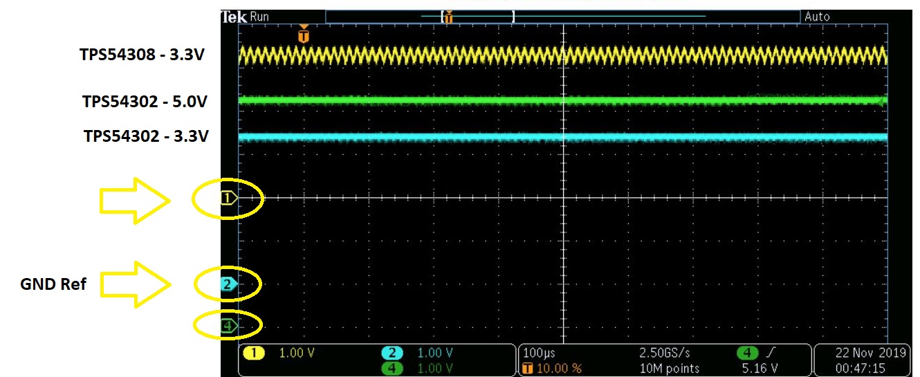
I have 2 TPS54308 regulators running off the same Input supply and seem to have some issues on the outputs when both are connected.

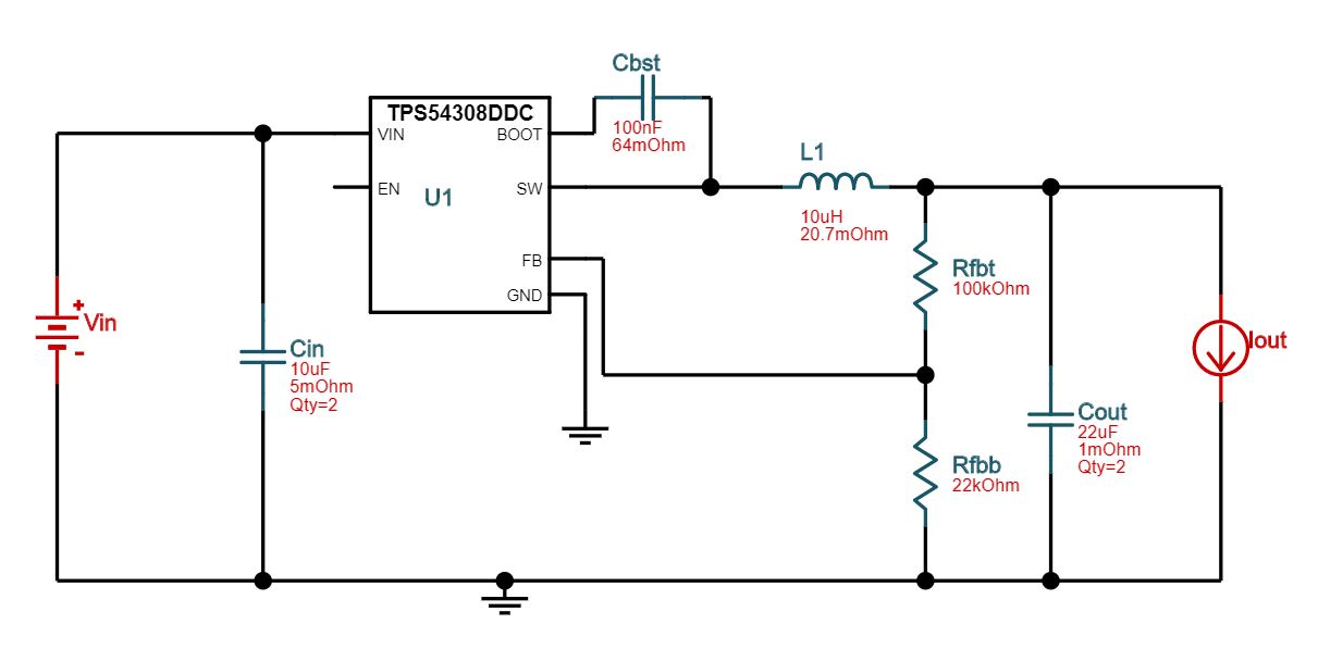
One outputs 3.3V and the other 5V. Using the Webench tool we calculated all the proper components and they work great on their own over the entire range.

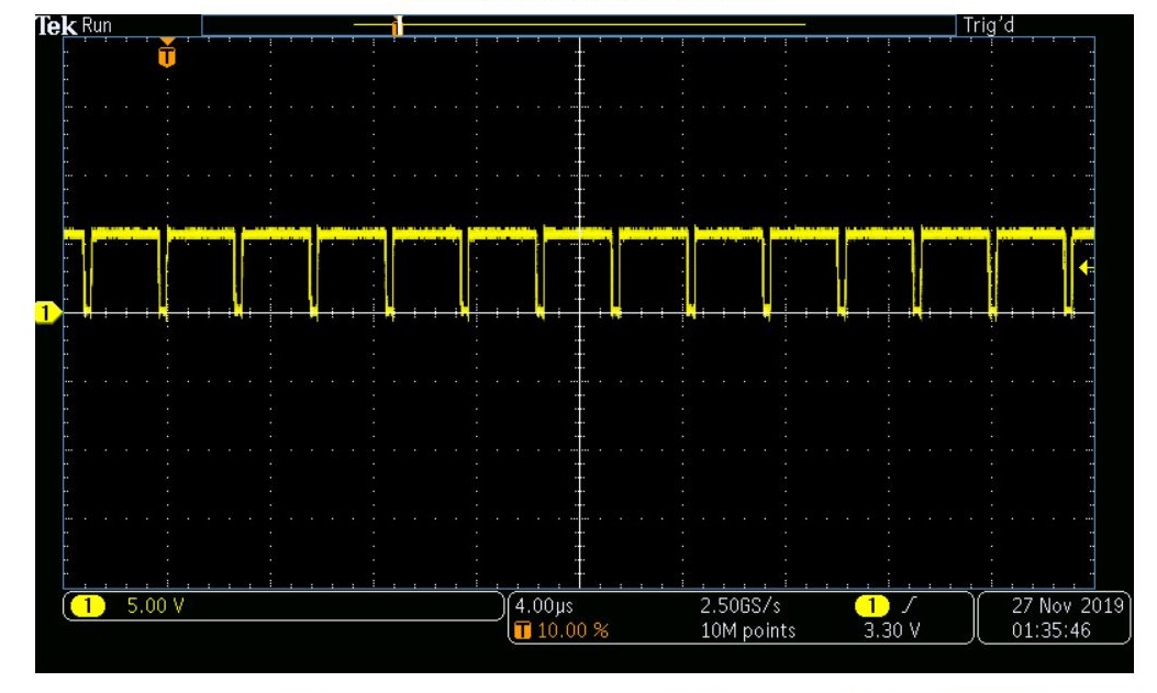
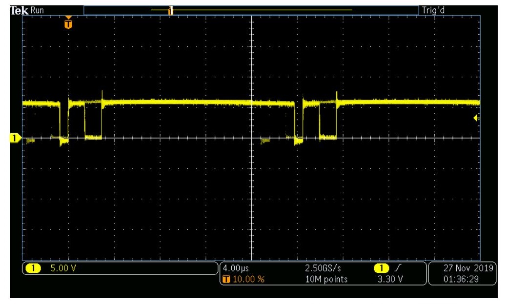
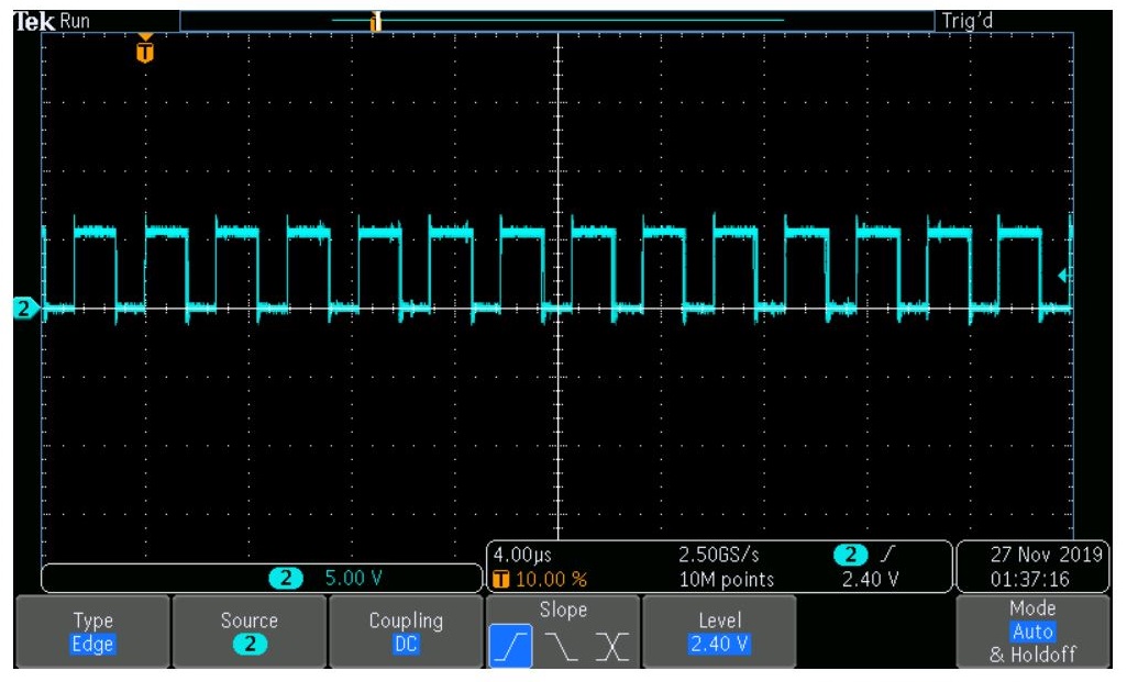
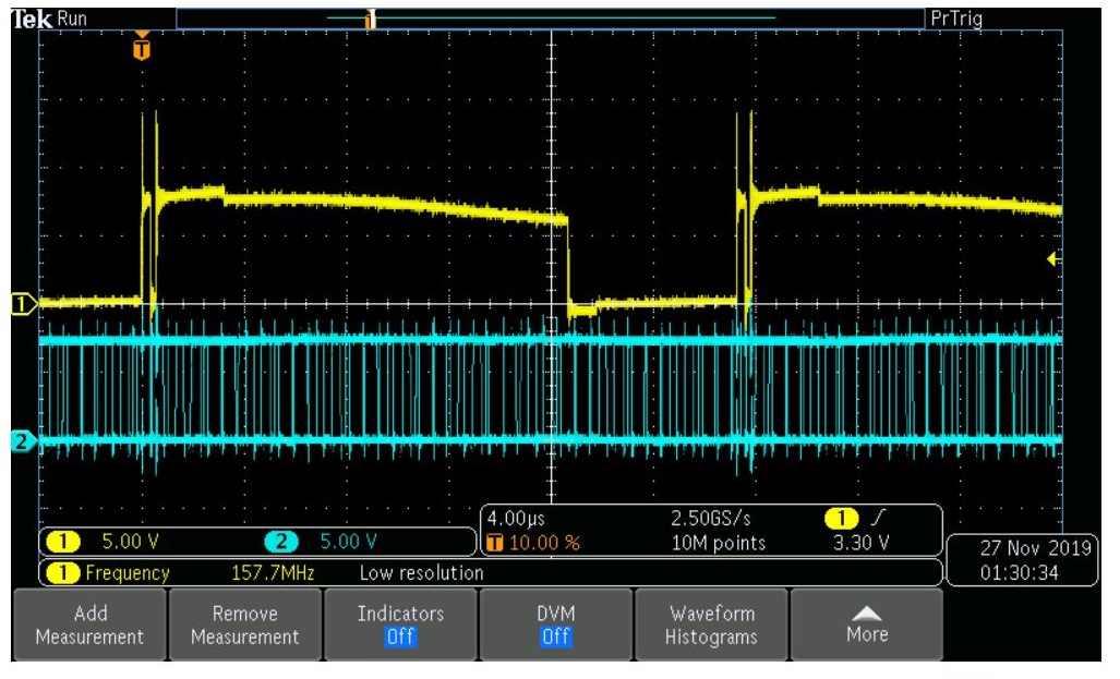
When using them at the same time there is noise in the output causing the powered devices to malfunction. Replacing the TPS54308 with a TPS54302 seem to prevent the noise issue and things work great tied to the same input. I currently have many PCB's made with the TPS54308 part installed and looking for a possible solution or reason this is occurring. Any ideas?

Thanks,

Bryan

  • Hi,

    Could you please share the schematic and layout? Let's review them.

    And what is the load current? it would be better to share the waveform.

    Shawn

  • Hi Shawn,

    Attached are the 2 schematic files used for 3.3V and 5V generation and a scope snapshot. You can see in the scope snapshot that the TPS54308 output has much more ripple than when using a TPS54302.

    The load on 3,3V is average 500mA and the 5V is average 250mA

    When a TPS54302 is dropped in place of a TPS54308 the entire circuit functions as intended.

    Best Regards,

    Bryan

  • Hi,

    It is strange, there is no issue for the schematic. What is the input voltage and where is it from?

    It would be better to test the SW waveform, so that we can better know what happened.

    Shawn

  • Hi Shawn,

    Attached are some scope shots from the SW pin (3.3V and 5V).

    Input voltage range is 6-26VDC - currently using 6-7VDC from a DC bench supply. Also tested on a 12V battery.

    Running at 6V seems to work fine and the system runs with about 49mA of current (running LED's). Adding more load does not seem to help or alter the test.

    When increasing the input voltage from 6.0VDC to 6.2VDC there is some strange effects that start going on. 

    6V the frequency is about 345kHz - all works fine.

    7V the frequency starts hoping around and seems unstable.

    5V SW Signal_1.jpg - Show the 5V SW pin 1-100sec after applying 6V

    5V SW Signal_100s.jpg - Shows the 5V SW pin 100sec after applying 6V

    3.3V SW Signal.jpg - Shows the 3.3V SW pin after applying 6V

    6-7-6V Switch.jps - Shows the SW pins of 5V(Yellow) and 3.3V(Blue) after toggling from 6V VIN to 7V VIN then back down to 6V....all within about 2-5 seconds.

    Dropping the VIN down to 6V does nothing to make it go back to normal and a full power cycle is required. I also noticed the unit will start to draw more power from the bench supply.

    Normally it will draw about 49mA but jumps to 210mA at 7V...even after dropping VIN back to 6V it never drops back to 49mA until power is fully cycled. 

    Any ideas what could be wrong?

    Best Regards,

    Bryan

  • Hi,

    Please check whether there is current limit for the power supply. And is there any other circuit on the input side? 

    In addition, you can remove the load of the board, and add load current by using E-load, then check if there is any issue.

    Please share the layout, let's review if there is any weakness.

    Shawn