


I'm using the TPS92692 as a Boost Converter for a LED application. The converter will control a string of amber LEDs at a certain point in time and a string of white LEDs at another point in time. The two strings will not be on simultaneously and will probably have different forward voltages. The output current is controlled via a microcontroller and an external DAC using the IADJ pin. The output current is monitored via a microcontroller to ensure correct current regulation. The requirement is to have a 5ms soft-start period and an enable/disable signal via the SS pin.
(1) After following the TI Boost calculator spreadsheet to determine the correct component (compensation) values, I have entered these values into my simulator and the system has an over-current IS fault as it exceeds 250mV. When using the compensation parameters of the Evaluation Board, the simulation appears to be functioning correctly, albeit exceeding my 5ms soft-start period requirement which is expected as 8ms is the quoted value in the documentation. How do I correctly configure my simulation in a methodical way so that the converter will function as I expect it to?
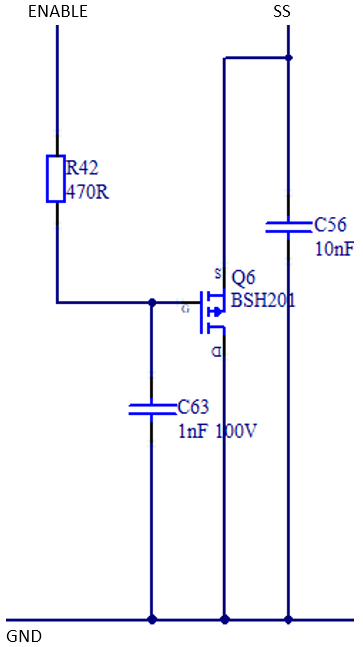
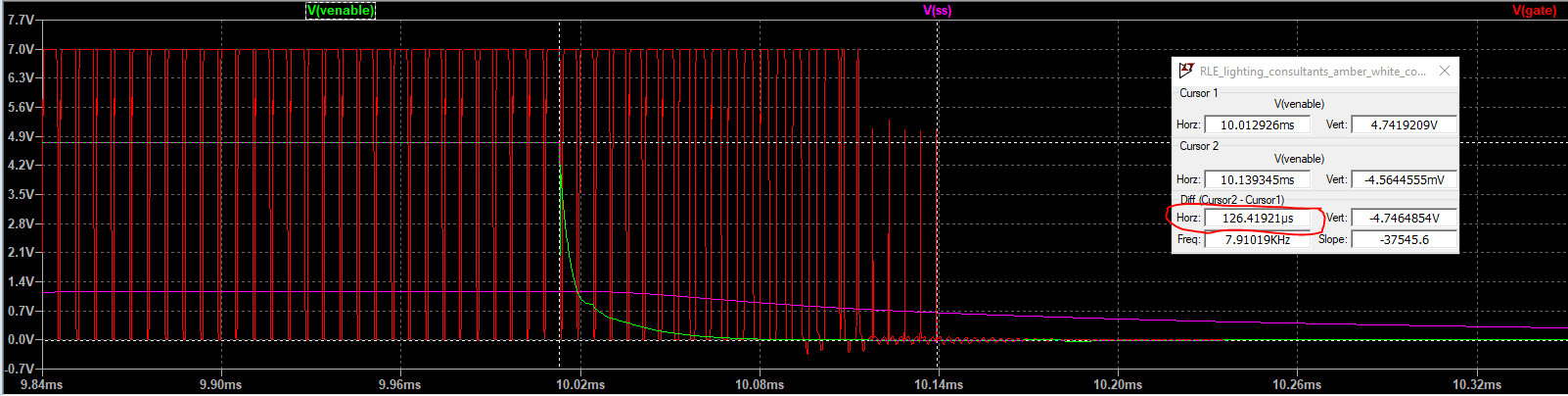
(2) I'm using a p-type MOSFET (BSH201) to enable/disable the converter on the SS pin however, it takes approximately 130us to fully disable the converter which is the time I apply a signal from the microcontroller to the time PWM switching ceases. I require a quicker turn-off (almost instanteous) as I'm turning on a bleed resistor on the output to discharge the output voltage below a certain threshold. How do I make the disabling of the converter more responsive?
(3) Can you confirm that a type 1 compensator would be more appropriate for this application?
