This thread has been locked.

If you have a related question, please click the "Ask a related question" button in the top right corner. The newly created question will be automatically linked to this question.

TPS22954: Enable voltage threshold used with LM3881

Part Number: TPS22954
Other Parts Discussed in Thread: LM3881

Hi Team,

My customer is planning on using our LM3881 to power the enable pin of the TPS22954. A concern of my customer is that the TPS22954 may turn on due to the Vflag votlage ramping up as it's input voltage ramps as well as seen in the table belwo for the LM3881.

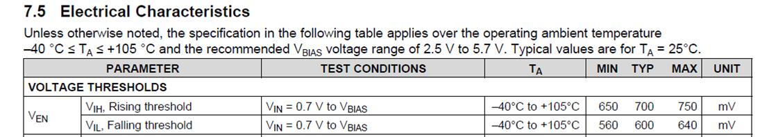
The Vflag will be connected to the EN pin of the TPS22954 which has the below threshold voltage with min of 0.65V which is close to the VFLAG voltage spike.

I was hoping to check if the TPS22954 would be able to withstand that voltage without turning on prematurely?

Thanks! 

BR,
Alfred

  • Hi Alfred,

    It looks like the flag voltage does rise to 0.65V from that graph. Could you confirm that this is indeed the case?

    I think there is a risk that the device can turn on but I think if the flag voltage rises and falls fast enough, the device will not have time to respond to the change. What is the period of time that the voltage will be at or above 0.65V?

  • Hi Shreyas,

    Thanks for the feedback! I will post another question in the forum for the details on the LM3881 Vflag rise. But to clarify on what you sat that the if it rises and falls fast enough, what is the usual response time for the EN pin of the TPS22954?

    Thanks! 

    BR,

    Alfred Logico

  • Hi Alfred,

    This depends on the value of the CT capacitor used but there is always a blanking time of 100us (tBLANK). This is a method of withstanding noise on the input

    If you look at Figure 52 on the datasheet, any "transient" under the blanking time does not affect the device.