Hi team:
About the datasheet of BQ24780S,I have some questions and need help.
1.In Charge current regulation,the accuracy is related to the charging voltage only in the following cases, while in other cases it is related only to the current.Why does this happen? (p6)

2.What is the meaning of the leakage mismatch in the figure below? (p6)

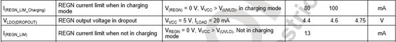
3.In Regn regulator,Why one of the test conditions is V(regn)=0V,What's the point of a current limit with the voltage=0? (p8)

4.Why is the REGN current limit different between charging mode and non-charging mode? (P8)
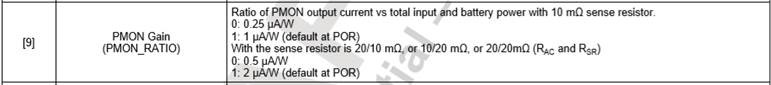
5. What is the PMON GAIN with the sense resistance is 5/5mΩ, 5/10mΩ, 5/20mΩ? (P27)
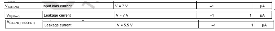
6.The meaning of V=7V in the figure below.(p10)
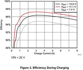
7. Why does the efficiency not increase with the increase of voltage?

Thanks!
Alice