This thread has been locked.

If you have a related question, please click the "Ask a related question" button in the top right corner. The newly created question will be automatically linked to this question.

LMG5200POLEVM-10: Programming TPS53632G over I2C

Part Number: LMG5200POLEVM-10
Other Parts Discussed in Thread: TPS53632G

Hi,

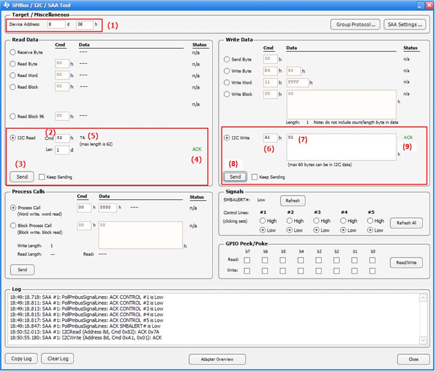
I am looking for the best method to program LMG5200POLEVM-10 from my computer. What USB adapter and GUI do you recommend? Is there any additional software needed to communicate with the TPS53632G? I am getting errors with the USB Interface Adapter EVM and default software

Thanks,

Ben

  • Hi Ben,

    I will leave this for someone in BMC team to comment since controller is from their team. Thanks!

    Lixing

  • Hello,

    I2C Programming: does the LMG5200POLEVN-10 have  an I2C port? You will need this to connect a TI USB-I2C interface box (USB-to-GPIO EVM) such that the user can test the I2C capability of the TPS53632G controller device. This interface box is not included with the EVM. It can be ordered from www.ti.com/.../usb-to-gpio.
    The user can communicate to the TPS53632G through this USB Interface adaptor using the Texas Instruments Fusion Digital Power Designer GUI.

    The latest version of the Fusion Digital Power Design software can be downloaded by typing "Fusion Digital Power Designer"

    http://www.ti.com/tool/FUSION_DIGITAL_POWER_DESIGNER


    Download the FUSION GUI and run the .downloaded installation application. Follow the installation instructions. This will install the driver and Texas Instruments Fusion Digital Power Design tool.

    The I2C GUI that is needed for communicating to the EVM can be accessed from the Windows Programs menu under Texas Instruments.

    Select the SMBus & I2C & SAA Debug Tool. The tool can be launched directly from here or for easier access going forward, it is recommended that the user right-click on the SMBus & I2C & SAA Debug Tool and choose “Pin to Taskbar” or “Pin to Start Menu”.
    The I2C communication is active when the 5-V bias supply is provided to the IC.

    For details on the I2C addresses and registers, see the TPS53632G Data Sheet. http://www.ti.com/lit/ds/symlink/tps53632g.pdf  The default I2C address for the TPS53632G is 40h.
    Follow the steps below to communicate from the host computer to the TPS53632G:
    • Connect the host computer to the USB-TO-GPIO adaptor with the supplied USB-to-Mini-USB cable.
    • Connect the USB-TO-GPIO adaptor at the I/O port of the EVM as indicated by the "I2C Interface" port  using the supplied ribbon cable.
    • Provide the 5-V bias supply (Power Supply #2) to the EVM.
    • The TPS53632G on the EVM is now ready for I2C communication.
    The Read and Write procedure using the I2C communication through the FUSION GUI is as follows.

    A snapshot of the GUI is shown in Figure 17.
    • Step (1): Enter the correct address (Default I2C device address ) of your device in either box (decimal or hexadecimal).
    • Step (2): To read data from a specific register address, enter the address of the register you want to read in the Cmd box.
    • Step (3): Click “Send”
    • Step (4): Ensure you see an ACK (NACK will indicate incorrect I2C communications).
    • Step (5): Data will be displayed in 2-digit Hexadecimal.
    • Step (6): To write data to a specific register address, enter the address in the box.
    • Step (7): Enter the data to be written in hexadecimal.
    • Step (8): Click “Send” in that same panel.
    • Step (9): Ensure you see an ACK (NACK will indicate incorrect I2C communications).
    A snapshot of the GUI is shown below. The device and register addresses in this snapshot is for illustration only.

    For details on the I2C addresses and registers, see the Data Sheet
    The I2C communication is active when the 5-V bias supply is provided to the board.
    Depending upon the test, the power supply and load can be turned on,
    The I2C communication can be used for the following purposes:
    • Change the boot voltage (prior to start-up). Write/Read Register 00h
    • Change output voltage (after start-up). Write/Read Register 00h
    • Monitor load current output. Read Register 03h
    • Change maximum programmable output voltage. Write/Read Register 04h
    • Change power state (PS) settings. Write/Read Register 06h
    • Change voltage change slew rate. Write/Read Register 07h
    • Read device TPS53632G lot code. Read Register 10-13h
    • Read device TPS53632G fault register. Read Register 14h
    NOTE: The no load output voltage can be changed using I2C programming. 

    The VID voltage as provided in the TPS53632G data sheet sets the internal DAC voltage.

    The output voltage is set by the DAC voltage, the external feedback resistors, the droop setting, and the load current. See the TPS53632G datasheet for complete information.

  • George,

    The EVM has jumper pins for SDA, SCL, and GND. I connected these to the USB Interface Adapter, followed the above steps and was able to read and write to the TPS53623G.

    Thanks for the help,

    Ben