This thread has been locked.

If you have a related question, please click the "Ask a related question" button in the top right corner. The newly created question will be automatically linked to this question.

LMZ36002: INH pin input current unspecified in datasheet

Part Number: LMZ36002

The LMZ36002 datasheet does not specify the input current for pin INH. What is this accross the temperature range?

Our circuit employing the LMZ36002 stops working above ~50DegC. This has been traced to the INH pin which draws more current as the ambient temperature rises. Consequently, our (current limited) enable signal voltage drops below the 2.8V threshold. What current does the INH pin expect?

  • Hi Konrad,

    What is your application (Vin,Vout, Iout)? Can you provide a schematic for me to review? Though I don't have that specific data, perhaps I might be able to catch something knowing the application and schematic. 

    However what I can say is, for a typical 24V input / 5V output, you can expect to operate at 105degC up to arough 1.5A at no airflow before needing to derate the output current. This is to prevent the part's junction temperature from exceeding 125C.

    Regards,

    Jimmy

  • Hi Jimmy

    Thanks for the quick response. Our input voltage range is 30-60V (lithium polymer battery) to power a battery management system. Output is 3v3 upto 1A. Application is an underwater battery for autonomous exploration, exposed to 600bar pressure. These electronics have survived 690bar exposure but not temperature testing so your help will be much appreciated.

    Note, we have three enable sources for the DCDC, an external signal 'IGN_FILT', an RTC derived signal and a uC enable. Only the external input signal has been tested at elevated temepratures to date:

    Our external enable signal (upto 60V) is conditioned as follows before reaching the LMZ36002:

    Our current line of thinking is that the signal conditioning circuit provides insufficient current to the INH pin to maintain operation at elevated temperatures. Is this reasonable?

    At room temperature and upto 40DegC all is fine, but then fails above this. This is replicated accross 3 of our prorotype boards. The PCB layout follows the datasheet recommended layout very closely so I doubt it is a thermal issue.

    Thanks

    Konrad

  • Hi Konrad,

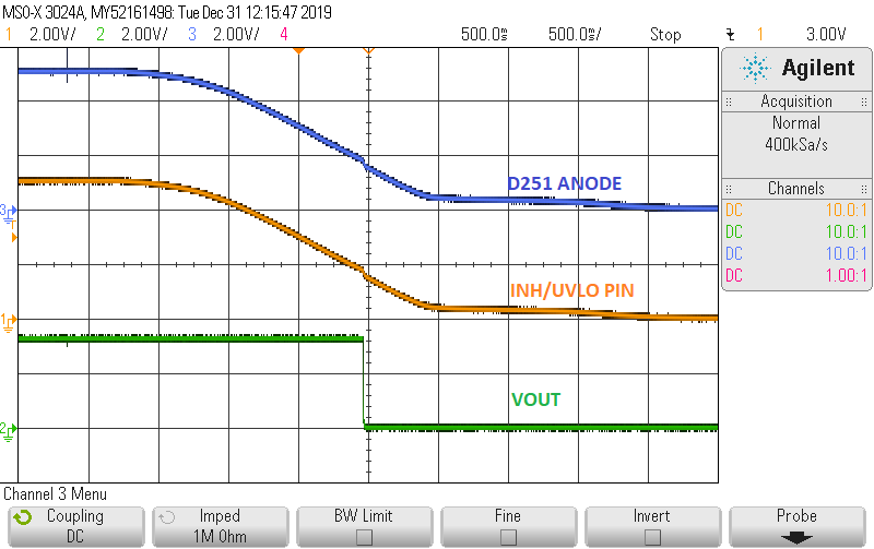
    So far the schematic looks okay. If possible can you provide me a waveform of VIN, VOUT, and voltages on anode of D251 (IGN_FILT) and cathode of D251( INH/UVLO) voltage at full load during the transition between room temperature to 50deg. If the INH/UVLO pin voltage is pulled below the falling threshold of 1.8V then it will disable. Something must be causing a drop in voltage below 1.8V on INH/UVLO pin at 50deg+ temperature after D251. 

    Another thing you can try is to directly connect INH/UVLO to PVIN and perform a temperature cycle between room and 50deg. Doing this will isolate the issue to only the power module. This will exercise the part's capability to regulate at 50degC in your application. The only thing different between doing this and your current application design that the INH is enabled externally from a 3.3V through a D251 diode. 

    Regards,

    Jimmy 

  • Hi Jimmy

    Thanks for confirming the schematics.

    I'm away from the office but have the following additions (sorry for poor formatting)

    The first column is the voltage applied to ignition.

    Second column is the corresponding voltage measured at INH at room temperature.

    Third column shows how low INH pin drops when the LMZ36002 alone is heated even when ignition is at 60v.

    Vign.       PinINH V.          PinINH V (heated)

    20.           7.7

    30.           11.9

    40.            16.0

    50.            16.2

    60.            16.2.        0.3

    There iNH pin pulls considerable more current when heated.

    I will run the

    tests you suggested in the new year.

  • Hi Konrad,

    I will try to contact the internal team to see if there might be any design considerations for INH pin input current during temperature cycle, though most are currently on holiday leave and such.

    For now I will wait for you to test my suggestion in the new year. I will keep this thread open and change the status to "Waiting for customer".  Please keep me informed of the test results that I had requested for. 

    Have a happy holiday break and new years.

    Regards,

    Jimmy

  • Hi Jimmy

    See below the power supply behaviour under the following conditions:

    Vin: 16V (power supply)

    Iin: 61mA

    Vout: 3v3

    Iout: 250mA

    WHen the package is heated, the INH voltage drops below the 1.8V threshold disaabling the power supply. 


    As suggested, I then connected the INH/UVLO pin directly to Vin (16V) through a Agilent 34410A multimeter. 

    • At room temperature: current into INH/UVLO pin is ~80uA. (microAmp)
    • When LMZ36002 package is heated with a heatgun, current into INH/UVLO exceeds 10mA (milliAmp). I plan to characterise the INH current at different temperatures in our environmental chamber next week.

    We would be very interested to hear what the current limit is for the INH/UVLO pin and suggestions on how to resolve this. We certainly were not expected the DCDC converter enable signal to need more than 10mA for reliable operation. 

    Regards

    Konrad

  • Hi Konrad,

    Most of the internal team are still on time bank but I will ping them again about the current limit on INH/UVLO when they come back to work. 

    As for my suggestion of disconnecting the external enable circuit, when you connect INH/UVLO pin directly to VIN and heat it with the heatgun, does the output voltage regulate or does it behave similar to the oscilloscope waveform you attached?

    Also I will order a LMZ36002EVM to try to replicate your condition (VIN= 16V; VOUT = 3.3V; IOUT = 250mA) and do a thermal cycle test with a controlled thermal chamber (25C room and 85C no airflow) to see if there are any issues with the output voltage regulation. This may take some time to get processed and shipped to me for testing but I hope to get the EVM sometime next week at the earliest. Just wanted to set expectations and transparent on when I expect to get the EVM to begin testing. 

    Regards, 

    Jimmy 

  • Hi Jimmy

    To clarify, with INH/UVLO directly connected to VIN, the output voltage remained in regulation when heated .

    Thanks for the update regarding your EVM. I'll see if I can dig out our EVM next week and compare behaviour.

    Regards

    Konrad

  • Hi Jimmy

    I've made progress on this issue and have isolated the cause of the problem we were experiencing.

    In the previous test where INH was tied to PVIN, I reported that the LMZ36002 would shutdown when heated. However, that setup still contained D251-253 in circuit. Checking the diode (MBR0520) datasheet, I found an unexpectely high reverse leakage current (upto 8mA) when heated (the diodes are physically close to the LMZ36002) which was causing the voltage at INH to drop below the enable threshold.

    To confirm this, D252 & D253 were removed, and the original ignition conditioning circuit used to enable the LMZ36002. With this setup, the voltage at INH did not sag when heat was applied and the 3v3 output remained stable.

    In short, the LMZ36002 was not the problem, but high diode leakage currents were causing the voltage at INH to sag below the enable threshold. We need to find an alternative diode with lower reverse leakage.

    I appreciate your time looking into this problem.

    Thank you

    Konrad

  • Hi Konrad,

    Thank you for the update and response. It is good to know that you were able to isolate the issue to the breakdown of the diode.

    If you have any further questions, please reply to this thread. Otherwise I will be closing this.

    Regard,

    Jimmy