This thread has been locked.

If you have a related question, please click the "Ask a related question" button in the top right corner. The newly created question will be automatically linked to this question.

TPS65218D0: Power output enable issue of PMIC

Part Number: TPS65218D0
Other Parts Discussed in Thread: TPS6521815, , BOOSTXL-TPS65218, TIDA-00478, IPG-UI

We will use only four DC-DC buck converter of this PMIC (DCDC1 to DCDC4) for XC7010 xilinx IC. Voltage levels and sequencing will be done by BOOSTXL-YPS65218 tool by using UI provide by TI for initial prototype.

After programming , we put this PMIC to our board, in this case i have following question :

1.  Should we use Push button switch for PB or AC_DET pin. or by simply pull up is sufficient to enable PMIC for PB/AC_DET and Power_EN PIN. We don't want to put in Push button in our design ?

2.VIO=5V is right or not....?

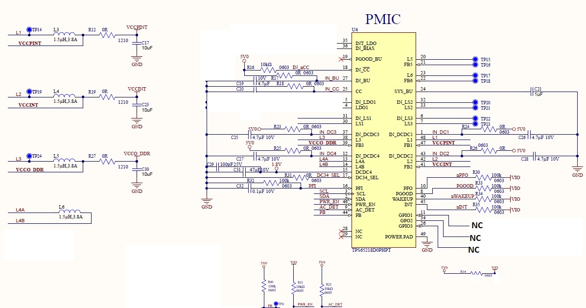
Please review the attached schematic....

  • Hi Satish,

    The expert for this device is currently out of office and will be returning on the 8th. Please accept a delay in his response.

    Best regards,

    Layne J

  • Ok..

    I will wait...

  • Satish,

    You can use TPS6521815 version of device if you want to program the PMIC on-board during production. TPS6521815 is same silicon as TPS65218D0 with different EEPROM programming. By default, TPS6521815 will not execute the power-up sequence. You will need to have connection for I2C (SCL, SDA, GND) to program the IC after 5V is applied to the system. After successful programming, you can power-cycle the board and it will power-on with the new voltages and sequencing.

    SATISH SOMANI said:
    1.  Should we use Push button switch for PB or AC_DET pin. or by simply pull up is sufficient to enable PMIC for PB/AC_DET and Power_EN PIN. We don't want to put in Push button in our design ?

    Connect AC_DET directly to GND & connect PWR_EN to 5V through a pull-up resistor. PB must also be connected to 5V through a pull-up resistor. When AC_DET = GND, no push-button is needed. 

    SATISH SOMANI said:
    2.VIO=5V is right or not....?

    VIO can different for each signal, but it should NOT be 5V. Typically, VIO is 1.8V or 3.3V because it is connected to an I/O pin on the SoC with power supplied from one of multiple VIOx rails. For example, PGOOD is an output from the PMIC that typically drives the nPOR input on the SoC. You would need to see which supply provides power to the nPOR signal and then match VIO for PGOOD to this supply rail.

    When you program units on BOOSTXL-TPS65218, you can see the effect of AC_DET=GND, PWR_EN=5V by setting switch S2=HI (PWR_EN) and S3=GND (AC_DET). 

    To match the Zynq-7010 programming outlined in the TIDA-00478 design, you can open the attached .json file in the IPG-UI to re-program ICs.

    218_map-01_XiZynq7010_v2__DISABLED.json

  • Hi Brain,

    Thanks for your suggestions.

    We are planning for prototype we will program our PMIC by using BOOSTXL-TPS65218 then we will mount PMIC on our board. At production , we will program our PMIC by distributor only (like Arrow....) not on board programming, we want....

    1. Then should we continue with TPS65218D0 or we will use TPS6521815. or if possible please suggest any PMIC which can take VIN=12V

    2. Any comments in schematic ??

    3.DC34_SEL is power up default state output levels. but in our case , we have already prograamed PMIC external then we will plan to put in our board then should to NC (No connect) to this Pin ?

    4. We will remains NC (not connect ) to SDA, SCL,L5,FB5,L6,FB6,IN_LS2,LS2,LS1,IN_LS1,IN_LS3,LS3,GPIO1,GPIO2,GPIO3,INT,WakeUP,PFO,PFI,IN_BU,IN_CC,PGOOD_BU,IN_BIAS,INT_LDO,CC , is it OK....Or some pin need to PU/PD …...Please guide us......

    Thanks & Regards

    Satish Somani

  • SATISH SOMANI said:
    1. Then should we continue with TPS65218D0 or we will use TPS6521815. or if possible please suggest any PMIC which can take VIN=12V

    Most PMICs for SoCs cannot accept 12V input unless they are for automotive, and even some automotive PMICs will require a 12V-->5V pre-regulator. We can recommend a pre-regulator if you are interested. 

    If you are using Arrow to program TPS65218xx devices, it does not matter which part # you use: Arrow is set up to program TPS65218D0RSLR and TPS6521815RSLR.

    SATISH SOMANI said:
    2. Any comments in schematic ??

    I will review schematic in more detail tomorrow. Please attach as PDF

    SATISH SOMANI said:
    3.DC34_SEL is power up default state output levels. but in our case , we have already prograamed PMIC external then we will plan to put in our board then should to NC (No connect) to this Pin ?

    Please connect DC34_SEL to GND (directly or through 0-Ohm resistor).

    SATISH SOMANI said:
    4. We will remains NC (not connect ) to SDA, SCL,L5,FB5,L6,FB6,IN_LS2,LS2,LS1,IN_LS1,IN_LS3,LS3,GPIO1,GPIO2,GPIO3,INT,WakeUP,PFO,PFI,IN_BU,IN_CC,PGOOD_BU,IN_BIAS,INT_LDO,CC , is it OK....Or some pin need to PU/PD …...Please guide us......

    I will suggest terminations for these pins when I do full schematic review.