This thread has been locked.

If you have a related question, please click the "Ask a related question" button in the top right corner. The newly created question will be automatically linked to this question.

UCC28630: Problems with to activate the DRV pin of UCC28630

Part Number: UCC28630

Hi all

I am trying to assemble a 150-W Flyback with input range from 85-270Vac

I found this scheme by TI. I know that is an old versión.

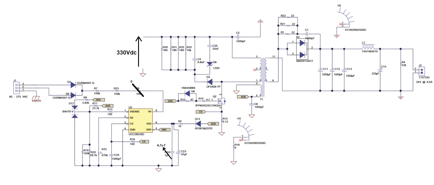
I dont know why but the DRV pin of UCC28630 never activates and then the mosfet never works

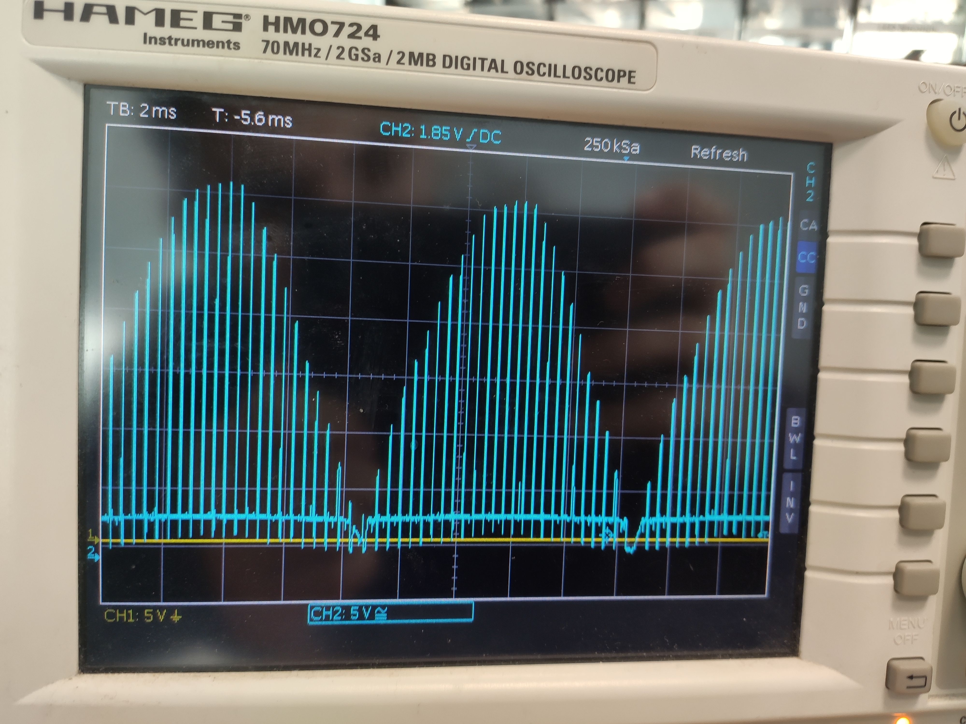
This is the voltage al HV pin:
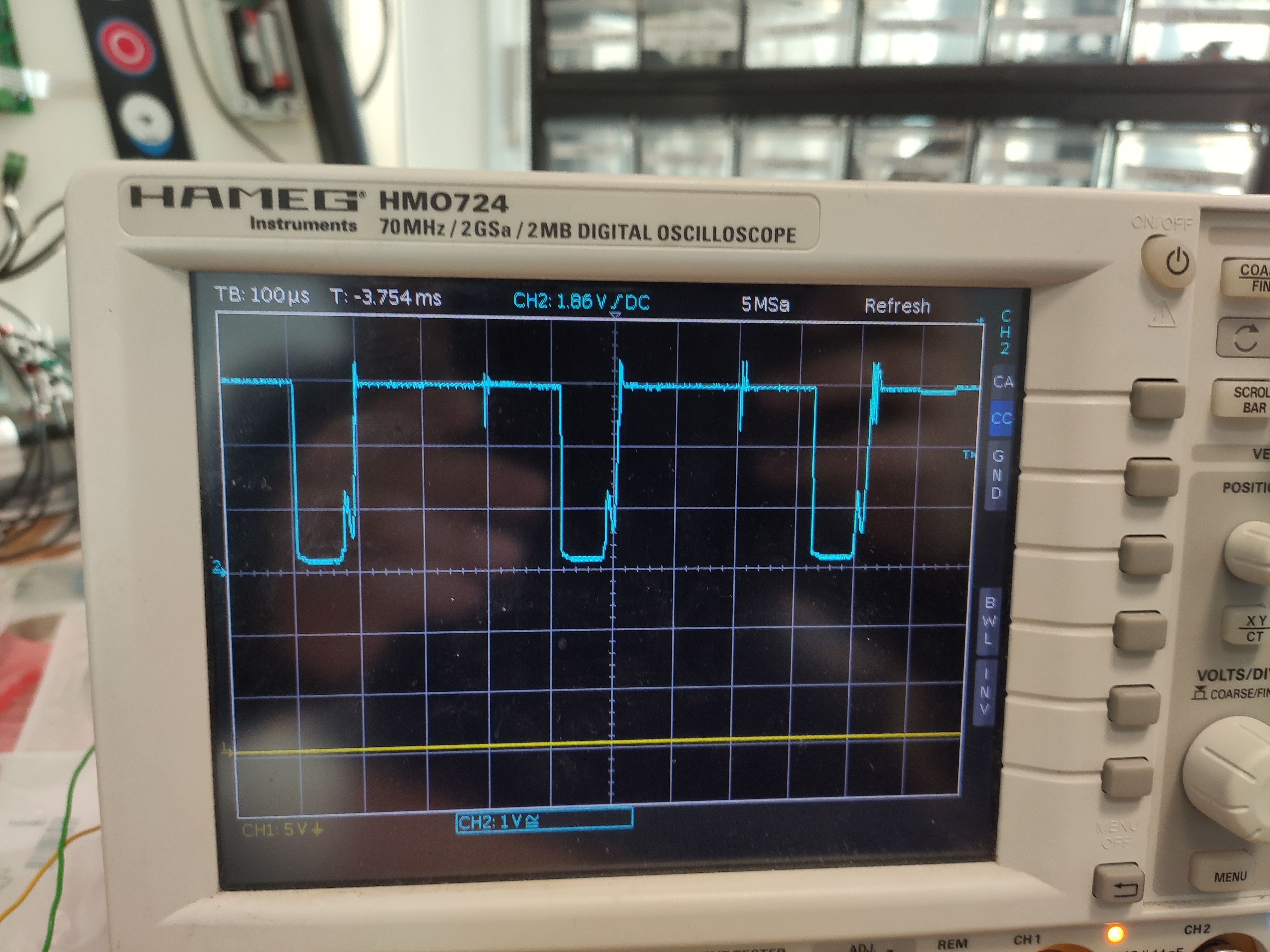
And in the VDD pin:

Where should the fault be?

Thanks in advance!!

  • You may refer to the datasheet page 17, Figure 16, for normal startup sequence. Your test result shows VDD did not reach startup VDD threshold, VDD(start). As VDD did not reach VDD(start), so no DRV.

    You need to find out why VDD cannot reach VDD(start).

    It is better you get an EVM to help your debugging.

  • Dear Hong Huang
    I have found an error in my connection.
    Now, with the correct connection in the VDD pin appears the graph that I attached.
    At startup there are 15V (a correct VDD start). Then the voltage decrease to 10V. That is correct?
    If we look with the oscilloscope on the DRV pin there is no voltage pulses.
    Do you know why?
  • You can refer to datasheet section 8.3.2 on page 18 to check if the input voltage is in correct range for power stage to start.

  • Hi

    I think the problem is somewhere else.
    If you see the first osciloscope image, there is the HV voltaje divided 10. That voltaje arrives to 300V.
    But the PWM of DRV is 0V.
    If the VDD pin ang HV pin are fine. On the other hand the pin CS is 0V.
    The problema shuld be in VSENSE or SD pin.
    In the SD pin i put a 470k resistor. 
    The problema Will be in VSENSE pin?
    Reguards
  • You need to refer to datasheet section 8.3.2 on page 18 to check. When VDD reaches its on threshold, there should be three pulses. If you do not see any pulses, that means your circuit has something wrong, or the device on your board is not functional, or your input voltage not high enough. VS pin could have something wrong but the initial pulses do not rely on VS resistor values.

    I suggest you apply for an EVM to help your debugging.

  • Thanks for all

    To find the problema we can take the ucc28630 and separate it from the rest of the circuit. Then feed the HV pin with the bulk voltaje and GND pin with the negative of the bulk voltaje. 

    If we not conect the rest of the pins, but we put the osciloscope in the DRV pin.  Should we see the PWM pulses?

    I don,t understand why the ucc28630 dont Works. Because de voltaje in to HVpin is 330V and the voltaje in VDD pin arrives at 15V at first 3 econs.

    Reguards

  • You need connect all required components to UCC28630 to make it work. If you cannot see any pulses from its DRV after VDD reaches its on threshold, can you change a new UCC28630 to try? If you still cannot see DRV initial three pulses, power off your board, and measure DRV to GND resistance, to make sure DRV is not shorted to GND.

    Again, I suggest you get an EVM to help your debugging.