This thread has been locked.

If you have a related question, please click the "Ask a related question" button in the top right corner. The newly created question will be automatically linked to this question.

TPS610985: Startup issue

Part Number: TPS610985

Hello,

I designed a new product that will use a single AAA battery cell to generate a 3.0V regulated power rail. This product will send some sensor data over the LoRaWan network and deepsleep the rest of the time.

I use the TPS610985 to generate the 3.0V main power rail as it seems to fullfill my power requirement.
The input voltage is in the 0.8V to 1.5V range and consumption is about 100mA max during Tx transmit. Deepsleep power consumption is about 1µA.

I build 5 prototype board and unfortunately the TPS610985 isn't working on 2 boards.

Input capacitance is 2uF and output capacitance is 41uF (10uF close to the chip with additional decoupling capacitors close to each critical components).
Startup time is about 7ms and input current limitation is set to 2A.
The TPS610985 start the boost converter when output voltage reach 1.8V as expected. I didn't expect this input voltage drop with 2A current limitation.

I measured the output voltage when startup fail. (1st channel - yellow) vs input voltage (2nd channel - blue).

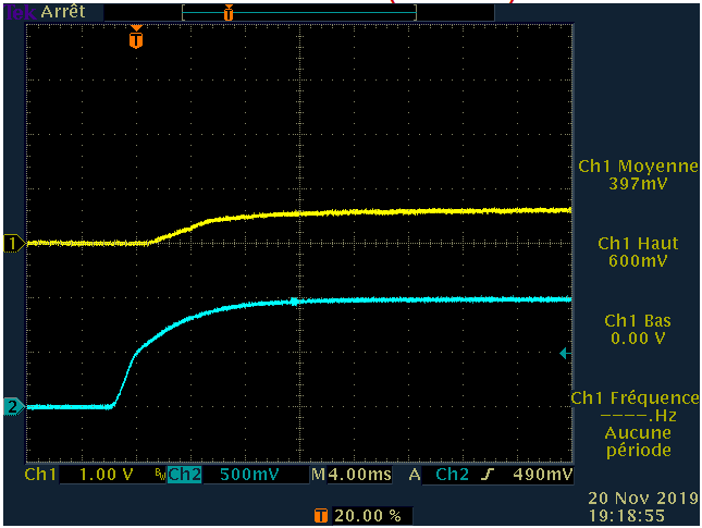
The power supply is locked and the output never reach the expected 3.0V. As output voltage is below 1.8V, the boost converter never turn on.
If I increase the input voltage to about 2.3V, the boost converter will start and I get the 3.0V output voltage as expected. Then it works even if the input voltage is decreased to 1V, but it will fail again if I power cycle the input power supply.

Could you please give me some information about what's going on when the TPS610985 is not able to start ?

Regards

Noel

  • Hi Noel:

    I'm out of office these days. Please allow me reply in next week. Thanks for your kind patience.

  • Its seems that my design is not compliant with some datasheet values.

    I updated it with the following values :
    Cout : reduced from 41uF to 22uF (Co1 = 22uF max in the datasheet)
    Cin : increased from 2uF to 10uF (Cbat = 5uF min in the datasheet)

    After those modification the issue was still there.

    Rin is equal to 22 Ohm in my design, that seems too low compared to the datasheet value (400 Ohm) and the evaluation module value (300 Ohm). I increased this value to 390 Ohm and the converter now seems to work.

    Here is a screenshot of a sucessfull start-up : (Blue channel is Vin, Yellow is Vout). Input voltage is provided by an external power supply set to 1V@2A.

    I'm quite surprised to get this Vin behavior when the bosst converter is starting. My external power supply is set to 2A current limit and I didn't expect to get such a pulse on the input voltage. Is it normal ?

    I will now update my BOM in order to improve Cin, Cout and Rin values but I didn't find any information about optimum Rin value in the datasheet.. Any clues ?

  • Hi Noel:

    Sorry for keep you waiting. And it's glad to see you have modified the circuit with datasheet, and it works now.

    For the recent waveform attached, I haven't seen such issue  before. Does blue signal drop every time during the test? Did you measure it at Vin pin or input power side? And is there any load during the startup?

    There is a typical startup waveform in datasheet as Fig 78. If we observe the Icoil, we will find it's less then 1A. The input current is close to the average value of it if the Cin is large enough. (Even if the Cin is too small, the Iin is hard to be larger than Icoil.)

  • Minqiu Xie said:
    For the recent waveform attached, I haven't seen such issue  before. Does blue signal drop every time during the test?

    Yes the blue signal drop every time, and all boards have the exact same behavior.

    Minqiu Xie said:
    Did you measure it at Vin pin or input power side? And is there any load during the startup?

    I measured the blue signal at Vin pin and there is no load at startup except the bypass capacitors and a few mA for the microcontroller.

    I will look at the Fig 78 and try to investigate.

  • Hi Noel:

    I'll recommend you to check the equipment setup firstly. And is the connection is well from the power supply to the board?

    It's better to measure the input current.