This thread has been locked.

If you have a related question, please click the "Ask a related question" button in the top right corner. The newly created question will be automatically linked to this question.

TPS40422: OCW and OCP keeps shutting down the part

Part Number: TPS40422

Hi, 

I have made a high power design with the TPS40422 operating in 2 phase mode. I have chosen a inductor with a L of 200nH and Rdc of 0.29mohm. I designed the TPS40422 to supply 35A per phase for a total of 70A in the 2 phases. When i am testing the part, i am using TI's Fusion Digital power designer to display the output current. I have adjusted the IOUT_CAL_GAIN to a value that is the closest to the 0.29mohm of the inductor resistance and also increased the IOUT_OC_WARN_LIMIT and IOUT_OC_FAULT_LIMIT to 45A and 49A retrospectively. 

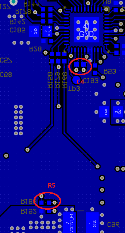
In my testing, i increased the load on the TPS40422 and at about 28A output (per phase as displated by the TI's Fusion power designer), i would get a IOUT_OC_FAULT_LIMIT and it would shut down the output voltage. I tried different values of R5 and C4 as per page 16 of the data sheet and it made no difference. In the end i settled with R5 = 1.5Kohm and C4 = 470nF which satisfies equation 2 on page 16 of the datasheet. I'm not sure why the part is shutting down as the IOUT_OC_WARN_LIMIT and IOUT_OC_FAULT_LIMIT is well beyond the displayed current draw.

In trying to figure this out, i increased the value of IOUT_CAL_GAIN to double of the inductor resistance and i am able to draw about 30A per phase without tripping the  IOUT_OC_FAULT_LIMIT. 

Can you please provide some guidance as to why the TPS40422 is tripping the IOUT_OC_FAULT_LIMIT and shutting down the output voltage when it is supplying less current then the set tripping point?

Thanks

  • Hi William, 

    TPS40422 is using inductor peak current (not average current) for OC detection. 

    When the Vcs (the voltage between CSP and CSN)  peak value is above IOUT_CAL_GAIN*IOUT_OC_FAULT_LIMIT, OC will triggered. 

    What's the initial C4 and R5 value you use when OC is triggered earlier?

    Thanks

    Qian

  • Hi,

    The initial values of C4 and R5 that i used was 2.1K and 330nF which is about equal to the L/Rdcr value that is described on page 16 of the datasheet. After reading the datasheet, it seems that i need to have a C4 and R5 combination that is slightly higher than the L/Rdcr to help reduce noise and that is when i decided to use the 1.5K and 470nF combination for C4 and R5. However even with these new values, the OC is triggered. 

    In my experiments if i increase the IOUT_CAL_GAIN to double that of my Rdcr, i would be able to increase the current draw. 

    Thanks

    William

  • Hi William, 

    Can you check if C4 of both channel is close to CSP/CSN pins?

    Also, can you share the layout how C4/R5 are connected to inductor pad?

    If noise is coupled to C4, OC will happen earlier.

    Thanks

    Qian

  • Hi,

    Please see attached two pictures of the placement of C4 and R5 as well as the tracks that is used to connect R5 to C4 that is on a inner layer. I tried to place C4 as close to the part as possible. In my design, i also added a 0ohm resistor on the CSxN pin as well which is located right next to R5.

    Thanks

    William

  • Hi William, 

    The layout example is available on datasheet page 62. 

    Can you check if CSP and CSN are connected to the inner side of inductor pad?

    Also, can you check if CSP and CSN traces are close to any noise source such as VIN copper, switch node copper?

    If you have differential probe, can you measure the voltage between CSP and CSN? Just want to check if there is noise on it. 

    Thanks

    Qian

  • Hi Qian,

    I followed the recommendations on page 62 of the data sheet when i routed the CSP and CSN nets, they are on the inner side of the inductor pads.

    The CSP and CSN signals do run under the SW node copper but these layers are separated by a layer of GND. Do you think that noise is coupling onto the CSP and CSN nets from the SW node copper even though it is separated by a layer of solid ground plane? Is there any way to help filter out this noise if this is the cause?

    Thanks

    William

  • Hi William, 

    I just sent you a private message with my email address. 

    Let's continue discussion by email. 

    Thanks

    Qian