This thread has been locked.

If you have a related question, please click the "Ask a related question" button in the top right corner. The newly created question will be automatically linked to this question.

BQ76PL455A-Q1: BQ76PL455 GUI - Unable to open COM port

Part Number: BQ76PL455A-Q1
Other Parts Discussed in Thread: BQ76PL455A,

I have installed the GUI to drive an evaluation board of the BQ76PL455 (our own, but very, very similar to the EVM).

I have a USB to TTL serial lead with a genuine FTDI chip, which comes up as COM7.

When I run the GUI it initially has a choice of com ports to use, with COM7 as default.

I click OK, then I get a message saying "Unable to open COM port", and the GUI closes after I click OK.

The COM port works fine (tested with a terminal interface + loop back).

Does anyone have any ideas? I'm struggling to get out of the blocks with this one.

  • Hi Mike,

    Welcome to the forum! Let's check first that your BQ76pl455A device is powered properly. Without the FDTI cable connected, and the BQ76PL455A-Q1 device powered (you can use 20V to start with), TOP pin voltage should be the voltage you are supplying (20V if you are supplying 20V) and you should see about 20uA current consumption (shutdown mode), unless you have a resistor ladder connected for the cells which would add more current. Then you can connect the FDTI cable and confirm that the voltage on VIO, RX and TX is 5V. 

    If that's all correct, then from software perspective, please make sure you install the FDTI driver from here: https://www.ftdichip.com/Drivers/VCP.htm 

    The cable we recommend to use is FTDI’s USB-to-TTL Serial converter cable to allow connection with a PC’s USB port. The recommended cable is available from FTDI (http://www.ftdichip.com), and the appropriate part number for the 1.8 meter cable is TTL-232R-5V.

    If the measurements are correct, you have installed/reinstalled the FDTI software and tried using the FDTI cable we recommend, and you are still having issues, please share your board schematic. 

    Best regards,

    Leslie

  • Hello Leslie,

    Thank you for your quick reply. I am using a genuine TTL-232R-5V cable (we use these, and the 3V3 versions, for other jobs too). I installed the latest driver from the FTDI site.

    VP does have 5V (well, 4.85V) present with the FTDI cable plugged in.

    The schematic and layout are attached as PDFs. There are a couple of errors on the board, which have been corrected (e.g. pin 70, VP, has a wire connecting to the NPN emitter now.

    I have a resistor ladder (of 1K0 resistors), and 24V across this to simulate the 7-series of 18650 cells, but I get the same COM port error whether this is connected or not.

    Thanks,

    MikePCB1138-1A_PCB.pdf

    PCB1138-1A_SCH.pdf

  • Hi Mike,

    VP seems to be quite a bit lower than spec (it should be 5.3V nominal). Do you happen to have the following connections made (from page 7 of the datasheet):

    "Connect to external NPN transistor's emitter and decouple with a 0.1-µF capacitor(3) to AGND and a 4.7-µF capacitor(3) in series with a 0.390-Ω resistor to GND. Locate decoupling capacitors as close to the VP pin as possible. Always connect VDIG to VP with 1-Ω resistor"

    Of particular note is including the 0.1uF decoupling capacitor as close to the VP and GND of the chip as possible, the 4.7uF cap and 0.390 Ohm resistor to GND, and the 1 Ohm resistor connecting VDIG and VP. Without these, functionality of the chip is not guaranteed.

    Regards,

    Vince

  • Hi Vince,

    I've added a0.1uF directly to the VP pin and AGND: same thing. (You can see in the schemtic that there is the 0.39R and 4.7uF snubber, and 1R0 to Vdig.)

    The 4.85V is coming from the USB serial lead. With no serial lead plugged in there is 0V on Vp, even with Vtop=24V.

    Just to be clear - does the message "Cannot open COM port" actually mean "Cannot communicate with BQ device"? I have assumed that the PC's COM port is the issue, not the BQ device.

    Mike

  • Hi Mike,

    With an incorrect voltage on the cable, it is possible that the COM port may have issues, especially when the voltage is forced to an unknown state.

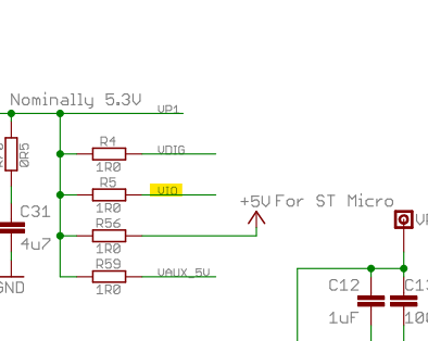
    I noticed in the schematic you provided that VIO is connected to VP/VDIG on the base device.

    This should not be connected to VP/VDIG on the base, but only the stack devices. See image below for EVM:

    Let me know if correcting this solves the issue!

    Regards,

    Vince

  • Hello Vince,

    Removing the Vio / Vdig / Vp (or any combination) doesn't change anything unfortunately.

    With 24V applied as a 'battery', I get no voltage on the emitter of the pass transistor.

    With the TTL232 lead plugged in, I get 5V on the emitter but still get a "Unable to open COM port" pop-up.


    I'm going to order the £260 (!!!) evaluation board and compare pin-for-pin.

  • Mike,

    While you wait for the evaluation board to arrive, can you confirm that you tried removing only the R5 resistor (leaving the other resistors on VP/VDIG) on your schematic from the base device?

    If not, please try this and let me know the resultant voltage on VIO.

    If so, please also ensure that the resistor to BAT (R1) is indeed 100Ohm as was notated on the schematic, as too high of a resistance can lead to an insufficient current to the device.

    Regards,

    Vince

  • Well, I've figured it out. I feel stupid, but it works....

    You definitely need to have the WAKE line working to wake the chip up: it wasn't.

    My board now happily talks to the eval board GUI.

    Thanks for your help.
    Mike