This thread has been locked.

If you have a related question, please click the "Ask a related question" button in the top right corner. The newly created question will be automatically linked to this question.

TPS610986: Large Output Capacitance Requirenment

Part Number: TPS610986

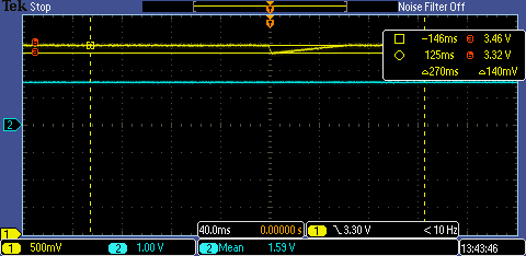
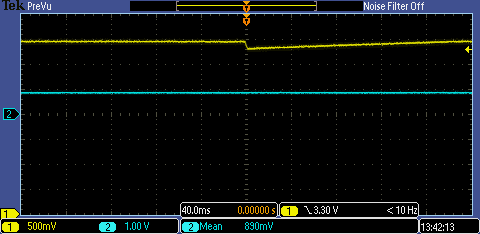
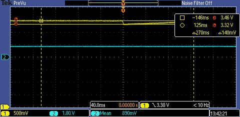
Based on testing my system, I have to add a large output capacitance. While running, the battery contacts can disconnect from the PCB for a few milliseconds, which can cause the boost to drop and the MCU to brownout. I have a 330uF capacitor to reduce the shutdown time so it can withstand the battery bounce.

I have attached the schematic. What should I be testing to ensure that this is a stable system? The boost is powering a BLE chip that can draw 6mA when advertising in low power mode.

I read that if there is large output capacitance, than a 2.2uF cap should be added next to the boost. Should I replace C3 with a 2.2uF cap?

A previous post suggested adding a resistor in series with the large cap.

  • Hi John,

    thank you for using our device.

    To ensure that system is stable measure your VIN and VMAIN during such an event on an scope. With this you can get a good feeling how much the output voltage drops. If you post a screenshot, we can look at that together.

    That additional 2.2uF cap should be close to the device. If C3 is very close you can use that, depends on your layout.

    regards,

    Moritz

  • Hi Moritz,

    C3 is very close to the boost so we should be good there. Below are the scope captures. I tested with VIN = 0.9V & VIN = 1.6V. The yellow trace is VOUT and the blue trace is VIN.

    1.6V VIN

    1.6V VIN with Cursors

    0.9V VIN

    0.9V VIN with Cursors

  • Hi John,

    I don't see a crank in the input voltage. Where exactly did do measure that? Or could you maybe triger on the input crank rather than the output .

    Can you please also measure the SW pin.

    thanks,

    Moritz

  • Hi Moritz,

    I will re-measure. What do you mean by crank?

    John

  • Hi Moritz,

    I re-measured at the advertisement packet transient. I added in the switch signal. Below is my measurement setup:

    The yellow line is VOUT, the blue line is VIN, and the purple line is Switch. I set up the VOUT and VIN scope traces to be AC coupled so we can look closer at the transients.

    This is a zoomed out snapshot of the voltage drop when the device sends out an advertisement packet.

    This shot below is zoomed into the initial voltage drop.

    This capture is further zoomed into the initial drop and the high frequency switching.

  • Hi John,

    appologies for the delay.

    To me the behaviour of the TPS610986 looks ok.

    It'll get reset though. As long as this and the 140mV drop on the output is not a problem for your solution you should be fine.

    How long are those battery disconnects? Always the same length?

    regards,

    Moritz

  • Hi Moritz,

    Thanks for the response. I think I am going to proceed with the larger capacitor.

    I think generally battery disconnects are about 20 - 30ms but I don't have any test data on that. Its pretty hard to recreate in the lab environment.

    John