This thread has been locked.

If you have a related question, please click the "Ask a related question" button in the top right corner. The newly created question will be automatically linked to this question.

TPS53647: 80mvppk ripple @~45kHz

Part Number: TPS53647

Hi TI,

We have used TPS53647 in one of our board for 0.85v generation.

Now, we have made the second version of this board due to some modifications in version 1 board.

This time we have also done PI analysis and after PI results we have added extra capacitors. Extra capacitors are highlighted with Red color rectangular in the attached schematic.

Now in second version of board, we are observing around 80mv peak to peak ripples @ around 45kHz in oscilloscope which were not there in version 1 boards.

For measurements, we are using small BNC cable which is directly soldered at output capacitors to remove the possibility of probe related measurements errors.

Below is the image of ripples observed on scope.

Will you please review the schematic and let us know the problem?0181.TPS53647.pdf

Thanks,

Lalit

  • Hi Lalit,

    sure. we will review. Would you please provide PWM jitter waveform also.

    Thanks.

    Regards,

    Rama.

  • Hi,

    In second version of boards we are observing around 80mvpkk ripples @ 45kHz at output of TPS3647,when load is connected to TPS53647.

    But if we disconnect the load, then ripples peak to peak voltage is around 5-6 mvpkk.

    But in first version of boards, even when load is connected to TPS53647 peak to peak ripple voltage is around 5-6 mvpkk @ switching frequency of TPS53647.

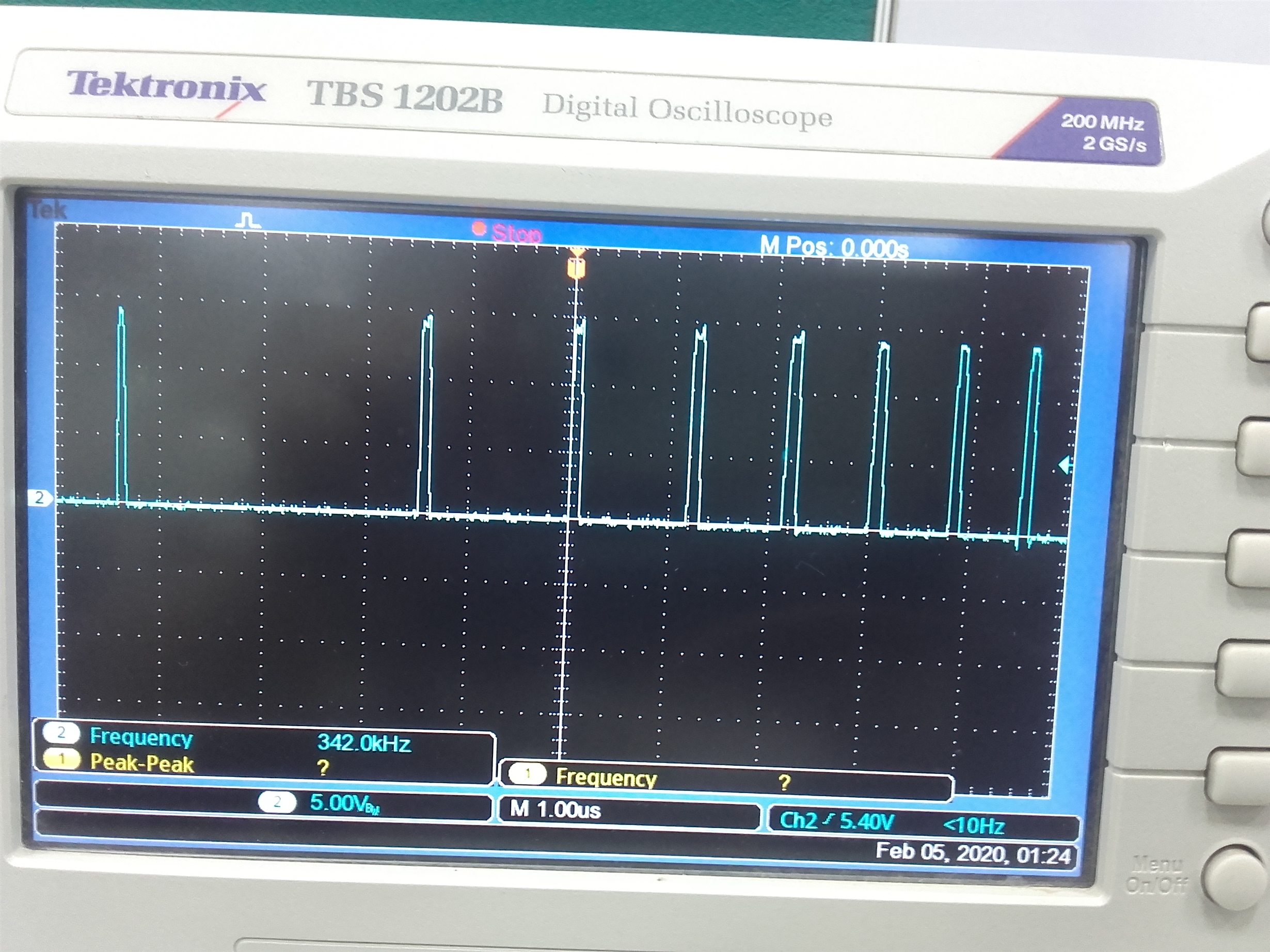
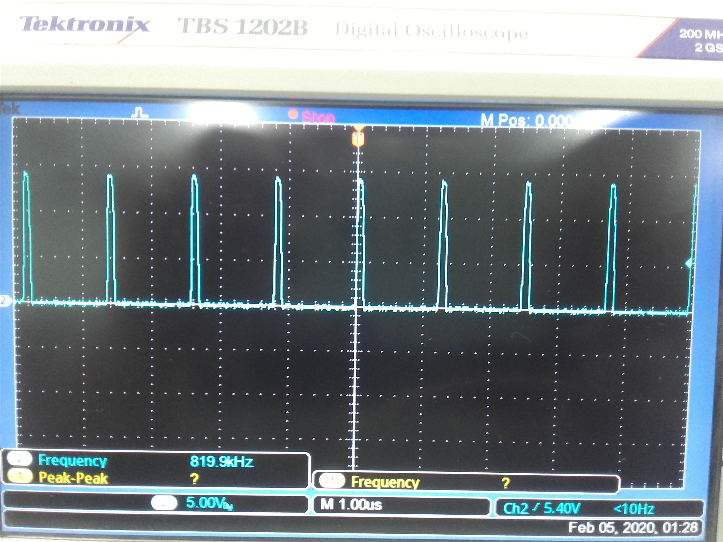
    I am attaching the pics and videos of PWM output of TPS53647 which is connected to PWM input of power stage IC CSD95372BQ5MT.

    1. With Load:

    2. Without Load:

    Right now switching frequency selection resistor Rf is 100k which is different from what is shown(30k) in schematic.But ripple voltage is same with both resistors.

    It looks like under load ,TPS53647 skipping PWM pulses, but I am not sure about that.

    So request you to please check the pics and videos of PWM signals for both cases i.e., loaded and unloaded.

    An early response will be highly appreciated.

    Thanks,

    Lalit

  • Hi Lalit,

    Thanks for waveform.

    Switching frequency set at 900kHz. would you please  change  Fsw=500kHz and check SS ripple at load.

    Please provide load value.

    Thanks.

    Regards,

    Rama.

  • Hi Rama,

    Previous Frequency was 500KHz only but with that also  ripple were more, then we had modified the frequency to 900KHz to see the trial whether the ripple will reduce or not.

    With 900KHz also the ripple are seems to be same. 

    Our load is :-

    Vout = 0.9V

    O/P Current = 30A Max

    Is our slope compensation components values are okay? 

    Since this problem was not in the Ver-1 board (We are only getting ~5mV ripple with full load) but now in second version of the we are facing this issue. We have only increased the capacitors at the output in the Second Version and no other changes was done.

    Kindly advice the possible cause of the issue.

  • Hi,

    We have changed the switching frequency to 500KHz but result is same.

    When board is fully functional the load is around 30A but as of now load is ~10A.

    Thanks,

    Lalit

  • Hi Lalit,

    Thanks for update.

    would you please provide  if there are any layout changes in version2, also send us layout files to ramasiddaiah.ti.com

    Regards,

    Rama.

  • Hi Lalit,

    Would you please update on this issue.

    Thanks.

    Regards,

    Rama.