This thread has been locked.

If you have a related question, please click the "Ask a related question" button in the top right corner. The newly created question will be automatically linked to this question.

BQ78350-R1: Programing the bq78350_R1 for the first time

Part Number: BQ78350-R1
Other Parts Discussed in Thread: BQSTUDIO, BQ76930EVM, BQ76940, BQ78350, BQ76930, , BQ76940EVM, EV2400

Hi there,

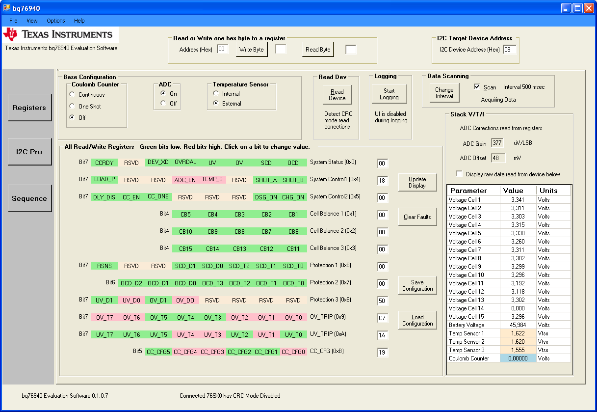
I have the bq76930EVM eval PCB. Unfortunately Ive burnt it and the BQstudio gave me wrong values on the battery cells voltages. Of course with a multimeter the voltage were fine. So I decided to replace the bq76940. Now the voltages are fine; but unfortunately, some seconds after the power up, the BQStudio lost the comunications with the PCB and show me that there is not device available. I have update the firmware to R1 and R2 versions without success; device lost some seconds after power up.

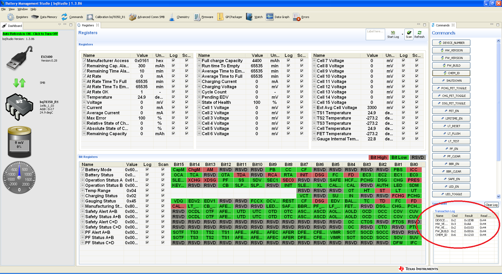
So I decide to replace the  bq78350 as well. I have assembled the bq78350_R1 (bought via Farnell, code 2507118). Now the BQStudio does NOT detect this new device at all.

I have check the solder pins and "seems" fine. So at this point I have to think about other causes. The first one is the firmware inside the bq78350_R1.

So, my questions are:

Texas Instruments, provide the bq78350_R1 properly programed? Even acquired via Farnell?

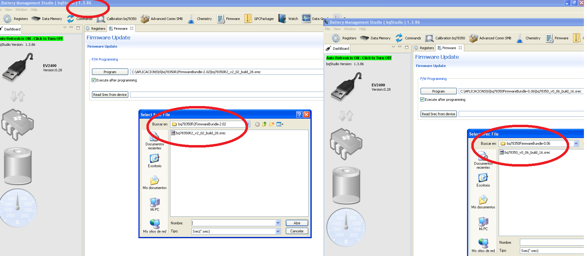
There is some way to ensure the firmware? I mean I have update the firmware on the original Eval PCB device; but now with the new one assembled, there is no way to link with it via BQStudio.

In other words, how is the procedure to update the bq78350_R1 device? I know the golden image with all the parameters; BUT how it will be update into the device?

thanks

  • Hi Albert,

    Are you following all of the steps in the Gauge Quick Start section of the BQ76930 EVM User Guide? http://www.ti.com/lit/ug/slvu925c/slvu925c.pdf

    When you describe the lost communication several seconds after powering up, it could be that a low voltage observed on one of the cells could be triggering Shutdown mode. It is important to update the AFE Cell Map in Data Memory with the number of cells (0x03FF for BQ76930EVM). 

    The BQ78350-R1 should come properly programmed. I am not sure why the new device is not communicating. Make sure to follow the setup steps in the EVM User Guide and check the voltage on the REGOUT pin of the BQ76930 (it should be 2.5V to power the BQ78350-R1). If you still cannot communicate, it might be a bad device or there could be an issue with the solder.

    Best regards,

    Matt

  • Hi Matt,

    Thanks a lot for your answer, nevertheless, no progresses; let me explain based on 2 point:

    a)

    I have replaced the bq78350-R1 and the communications have been restored!!!! Perfect!!!!

    Unfortunately, the cell voltages were wrong. I have 14 cells, 11 were set to 0V and 3 set to 3300mV; in addition the temperature sensors RT1,2,3 to -123ºC!!! Really strange.

    At this point I have made some hardware checks: I have measured the cell voltages on the input pin device and all of them were set to 3,3V; the REGsrc=48V, the REGout=2.5V; The BAT=48V, I can see the I2C communications between devices bq78350-R1 and bq76940, Cap3-VC10x=3,3V; Cap2-VC5x=3.3V and finally Cap1=3.3V.  So seems all correct!!!!

    Then I have realized that I updated the bqStudio to 1.3.86. So, my next step is restore the previous version v1.3.52 which run well, I mean showing the cell voltages properly. I have tried to download from your TI page but is not available.

    ---> So, could you send me a link where download the previous bqStudio version?


    b)

    After the previous steps, I update the bq78350-R1 to V0_06_build_16 with the same results. After I have update to R2_V2_02_build_28 and the communications HAVE BEEN LOST AGAIN!!!! And of course, the device is disable at all. Attach a screenshot.

    I assume that the R1,R2 and all the versions are 100% compatible with the device bq78350, bought WHEREVER. That’s correct?

    So, in my opinion the R2 DOESN’T RUN even the worst, disable the device!!!!

    --->Could you check it? I mean could you update from R1 to R2 with the BQ76930 EVM eval board?

    thanks a lot for your time.

  • Hi Albert,

    I am confused. The BQ76930 is a 10S device, but you are connecting 14 cells? The BQ76940 supports up to 15 cells, so you should be using the BQ76940EVM. Can you verify which EVM you are using?

    There is nothing wrong with the BQ76930-R2 or R1 firmware, so I suggest debugging the EVM first before making any changes to the firmware (especially if your BQ78350 is shutting down since it could shut down while you are writing firmware). The latest versions of BQStudio also work well with this EVM, so there should be no need to switch back to an old version. Once the hardware issue is debugged, I recommend always using the latest firmware and BQStudio version. 

    Best regards,

    Matt

  • Hi Matt,

    My Eval PCB is BQ76940EVM; so 15 cells, nevertheless the #14 is disable externally with a short.

    I have done two test:

    1) With bq76940 Evaluation Software.Connecting the EV2400 I2C por;t to Eval PCB I2C (J8) port. See attach picture. Where you can see the cells voltages set to 3.3V less the #14.

    2) With bqStudio.Connecting the EV2400 SMB por;t to Eval PCB SMB (J17) port. See attach picture. Where you can see the cells voltages are set to 0V. Here as well, you can see some comand request.

    Obviosly the two test runs under the same conditions, in fact just some seconds between them.

    Why bqStudio doesn't give the right cell voltages?

    Seems, that BQ76940 device is measuring the cell voltages properly ; NEVERTHELESS the BQ78350 lost the measuremetns. Any idea?

  • Hi Matt,

    mmmmmmmmmm........ sorry. has been my fail.

    Red means activated; green not activated.

    R1,R2, and bqStudio running as expected.

    sorry again

  • Hi Albert,

    Everything looks correct in your BQStudio screen capture except for the Cell voltages. That seems very strange. The only way I can reproduce this result is to set the AFE Cell Map on the Data Memory screen to 0x0000 and then cycling power on the device. If you AFE Cell Map is set correctly, you should be able to see voltages reported on the cells. 

    Regards,

    Matt