This thread has been locked.

If you have a related question, please click the "Ask a related question" button in the top right corner. The newly created question will be automatically linked to this question.

UC3845: Input Resistor and Capacitor Calculation

Part Number: UC3845

Hi,

I have designed an circuit on webench and It work well. There is no problem. I get 55V , 1.2A output.

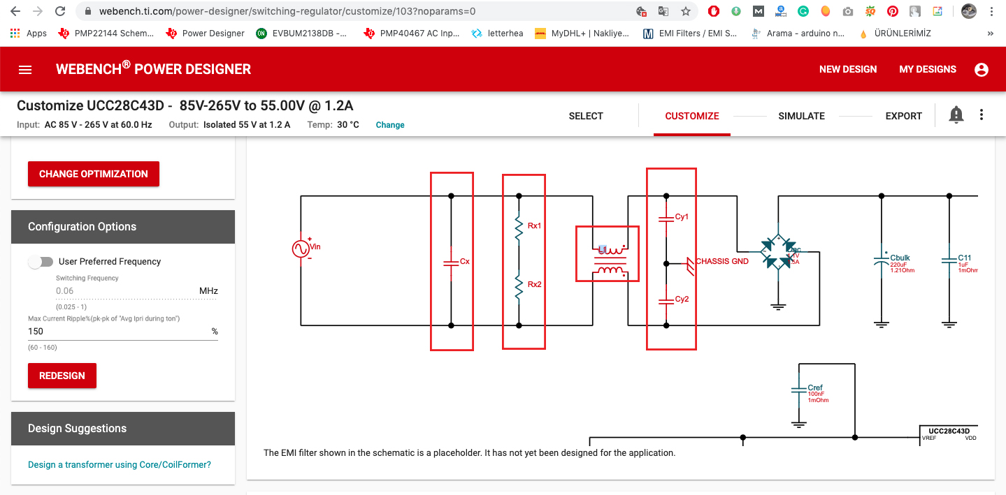
I need your support to understand the filter area. Because Webench does not give any information for them.

• Which value should I use for CX?

• Which value should I use for Rx1 and Rx2? What is the mission of this part?

• Which value should I use for L1?

• Which value should I use for Cy1 and Cy2? Should I connect the EARTH INPUT center of them? Does Chassis GND mean Earth? 

• Should I use varistor in input area? If yes, which value is ok for my circuit?

I am not a professional designer so I need your support. According to your reply, I finish my GERBER to produce my PCBs.

Best Regards

  • Hello, an expert will get back to you tomorrow. —— Teng

  • Hello,

    Thanks for your interesting in TI's part.

    All of components you highlighted in the schematic are for EMI , there is no commonly used value for each part for different application , PCB layout and mechanical size. so I can't reply you directly . the purpose of Rx1 and Rx2 are for discharging the X-cap Cx to a safety voltage when AC dropped in a specific time. that is different requirement in different safety standard , for example In IEC60950 , The voltage on X-cap should be discharged to 37% in 1second.

    but for IEC62368 , The voltage on X-cap should be discharged to low than 60V in 2 seconds . so the Rx1 and Rx2 value will be decided by Cx value and which safety standard your product should follow.

    For CY1 and CY2 , except for the effect of EMI , you also need consider leakage current requirement by which safety standard you have to follow .which will limit it's maximum value. Usually , if your input cable have 3 wires , N, L and Earth , you can connect the Chassis GND to Earth.

    Whether or not a varistor needed in your design depends on your power converter application environment . usually the surge ,lightning spec. will tell you that.

    About how to design EMI filter , I suggest you to search it on website , here is a training video on TI.COM.

    https://training.ti.com/how-design-input-emi-filters-automotive-dcdc-converter?keyMatch=EMI%20FILTER%20DESIGN&tisearch=Search-EN-everything

    Hope can help you.