This thread has been locked.

If you have a related question, please click the "Ask a related question" button in the top right corner. The newly created question will be automatically linked to this question.

BQ79606A-Q1: OVP & UVP for BQ79606

Expert 2385 points
Part Number: BQ79606A-Q1
Other Parts Discussed in Thread: BQ76200, TIDA-00792, , INA240

Hi,

I would like to add the Primary protection for OVP & UVP into the BQ79606 reference design? As I've check the BQ79606 reference design I couldn't find how it protect the OV & UV.

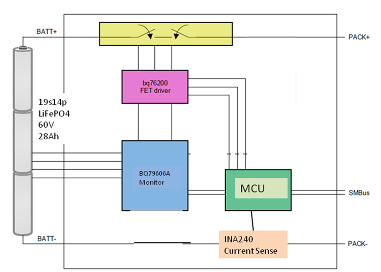
Do I need to add the BQ76200 as a primary protection such as below? With reference from TIDA-00792.

Please help to advise the proper integration of this feature into the TIDA-01537.


  • Hello,

    BQ79606A-Q1 is a battery monitor device. It monitors the batteries and has capability to detect OV/UV on the cells, but it is purely a slave device, meaning it won't make any decisions. The BQ79606A-Q1 sends the information to the microcontroller and the microcontroller in the system makes the decision on what to do with the OV/UV event. 

    To control the FET driver you have a few options: you can control it directly from the microcontroller, from the GPIOs on BQ79606A-Q1 or from the SPI master on BQ79606A-Q1. If you use the GPIO or SPI master, notice that the microcontroller still needs to communicate to BQ79606A-Q1 to set the desired output on the GPIO pins since the '606 device itself won't make any decisions, everything comes from the MCU. For more details refer to section 8.5.2 General Purpose IOs and SPI in the BQ79606A-Q1 datasheet.

    Regards,

    Leslie

  • Hi Leslie,

    Thanks for the advise, may I know how about the current sensing portion? Is it same as OV/UV protection or need to add additional device?

  • Hi Electrobud,

    For current sensing, you will either need to use an external INA device interfaced to the GPIOs of the bq79606A or some other additional device.

    Regards,

    Taylor

  • Hi Taylor,

    Thanks for the advise, can you help to check is the INA correctly placed into my blocks?

  • Hi Electrobud,

    You'll need a sense resistor between PACK- and BATT- (as shown in the first image you shared) and then connect the inputs of the INA240 device across each terminal of the resistor to be able to measure the voltage drop. To monitor the voltage, you can either connect the output of the INA240 to a GPIO in the MCU, or you can use a GPIO in the BQ79606A device. You might find it helpful to review the technical documentation available for INA240 device: http://www.ti.com/product/INA240/technicaldocuments

    Best regards,

    Leslie