This thread has been locked.

If you have a related question, please click the "Ask a related question" button in the top right corner. The newly created question will be automatically linked to this question.

LP55231: LED cannot turn on no matter by setting register 4 or 5

Part Number: LP55231

Dear team,

Nice to contact to you, I got a LP55231 with symptom from customer R&D.

All the process is provided as below,

1.Turn on chip (register 01h bit[6])

2.Turn on charge pump (register 36h bit[4:3])

3. Set PWM at 255 (register 16-1B) to 11111111

4.Set current at 175 (register 26-2B) to 10101111

5.Set PWM at 0 (register 16-1B) to 00000000 Or Set current at 0 (register 26-2B) to 00000000.

When I set register 16-1B or 26-2B to 0 one by one, LEDs are off all the time. I can still read register setting at this time, but LED cannot turn on no matter by setting register 4 or 5, register 16-1B, and register 26-2B until re-turning on power.

Do you have any advice for us to check the IC’s status when LED off happens?


Schematics as below, we use 3ch for one LED. In our system, total 2 LP55231 and 5 LEDs.
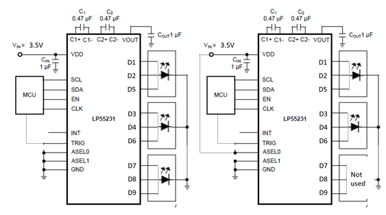
Thanks.

Kane

  • Hi Kane,

    I am not so understand the description 'I can still read register setting at this time, but LED cannot turn on no matter by setting register 4 or 5, register 16-1B, and register 26-2B until re-turning on power'. If process 3 and 4 is re-set, the LEDs should turrn-on. Could you help to ask customer read all registers at the situation LEDs are wrongly all off.

    BTW, do you know why customer set [D1,D2,D5], [D3,D4,D6], [D7,D8,D9] as 3 group? Normally we would set as [D1,D2,D7], [D3,D4,D8], [D5,D6,D9], because D7, D8, D9 is connect to VDD and suit for red LED. It just curious and should not relate to this off issue.

  • Hi Hardy,

    Thank you for your comment, please see my updates with customer as below:

    After finishing process 3 and 4, LED is turn on.

            Then, we want to close LED for a while, so we can use alternative ways,

    1. register 16-1B to 0. (PWM control to 0)
    2. register 26-2B to 0. (Current control to 0)


    Setting register 16-1B from 255 to 0 for LED off. Step one by one as below,

    1. Register 16 to 0.
    2. Register 17 to 0.
    3. Register 18 to 0.
    4. Register 19 to 0. We found that register 1A and 1B set to 0 at the same time.

    After that, we set all channel PWM back to 255, but failed, PWM always at 0, it means LED cannot turn on.

    I also try to set register 04/05 to 255, it still failed.

    This moment, we can read all IC’s register setting.


    Until we replug power, LED can be turn on, but LED turn off again through above whole process.


    Please let me know which state’s register you need. Just LED are wrongly all off?


            For schematics design, we don’t use red LED.

            [D1-D6] is using higher Vf LED, so connecting to charge pump output.

    [D7-D9] is using lower Vf LED, so connecting to VDD directly.

            We use 3ch to 1LED now.

    1. [D1,D2,D5]
    2. [D3,D4,D6]
    3. [D7,D8,D9]

            We reserve another solution for 2ch to 1LED, if we don’t need to higher current.

    1. [D1,D2]
    2. [D3,D4]
    3. [D7,D8]

    Kane

  • Hi Kane,

    For confirmation, during the process 1)Register 16 to 0; 2)Register 17 to 0; 3)Register 18 to 0, LED1-3 were turn off one by one. But after 4)Register 19 to 0. We found that register 1A and 1B set to 0 at the same time, means that customer did not write 0 to register 1A and 1B but channel 5 and 6 also turn-off? That is weird. Maybe other registers were wrongly written by this process. Could you ask customer do below 2 tests.

    1) Read registers before and after 'we set all channel PWM back to 255'.
    2) After wrong state happened, try to re-set Chip_EN and Charge Pump_EN to see if it can turn on the LEDs again.

  • Hi Hardy,

    Please see my customer's update as below:

    1)    Read registers before and after 'we set all channel PWM back to 255'.

    Please check attachments for register status for all step.

    For last step, you can find that even D6 PWM still at 255, Voltage of D6 is tiny.

    D6 is no output to LED.

    2)    After wrong state happened, try to re-set Chip_EN and Charge Pump_EN to see if it can turn on the LEDs again.

    1. Re-set Chip_EN , it can turn on LED again.
    2. Re-set CP_EN , Fail to turn on LED again.LP55231_20200302.xlsx
  • Hi Kane,

    This is strange that should not happened at normal device and I also cannot duplicate it on EVM with customer's step. Did this abnormal behavior happened at another IC? 

  • Hi Hardy,

    I only got one LP55231 with this situation.

    Or should I send this IC for FAE to check the status?

    Thanks,

    Poyi Lee. 

  • Hi Poyi,

    For confirmation, I saw there are two LP55231 in the system and you mean that only one have this issue right? In this case I suspect this one may be abnormal or damaged. You could contact FAE for further failure analysis request.

  • Hi Hardy,

         Yes, another one is work normally.

         I'll contact FAE directly.

         Thanks, Poyi