This thread has been locked.

If you have a related question, please click the "Ask a related question" button in the top right corner. The newly created question will be automatically linked to this question.

TPS59124: Power Good not coming up

Part Number: TPS59124

Hi, I have a PCB design that successfully utilises the TPS59124 (1000's of operational boards), however we have found that a few boards that were kept in storage for 12 months no longer power up successfully.

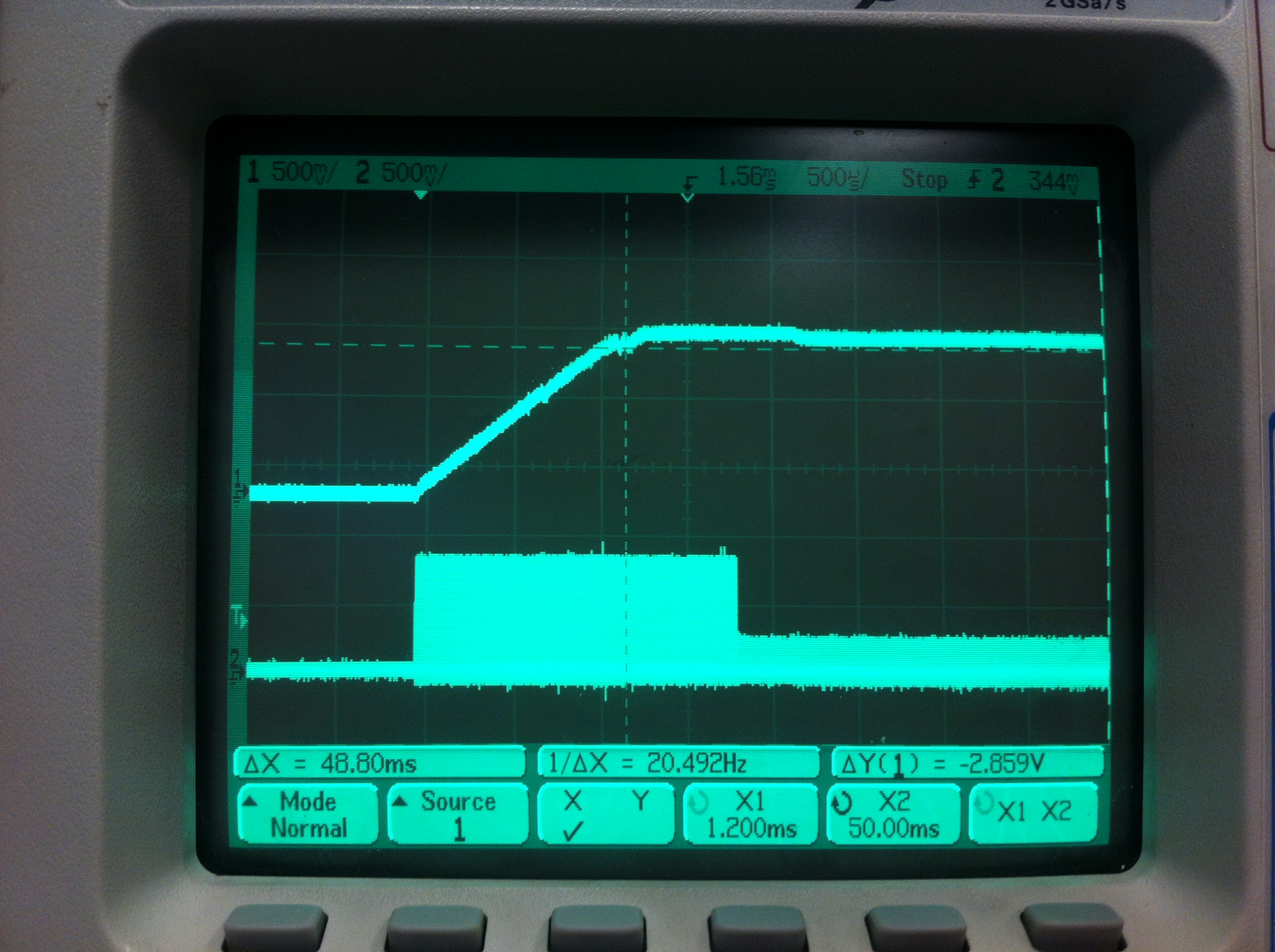
The regulator produces the correct voltage, but the PG line does not go high. Sometimes just one half of the regulator is affected, sometimes both sides are affected.

We baked the problem boards prior to reworking them (60 deg), and noticed that baking alone cured the problem.

Could the characteristics of the device change slightly with moisture level?

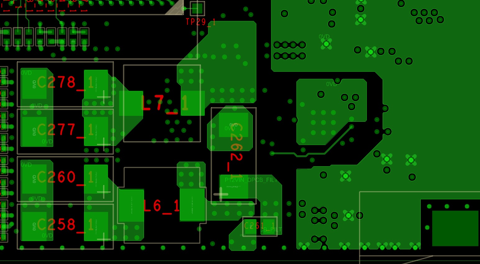
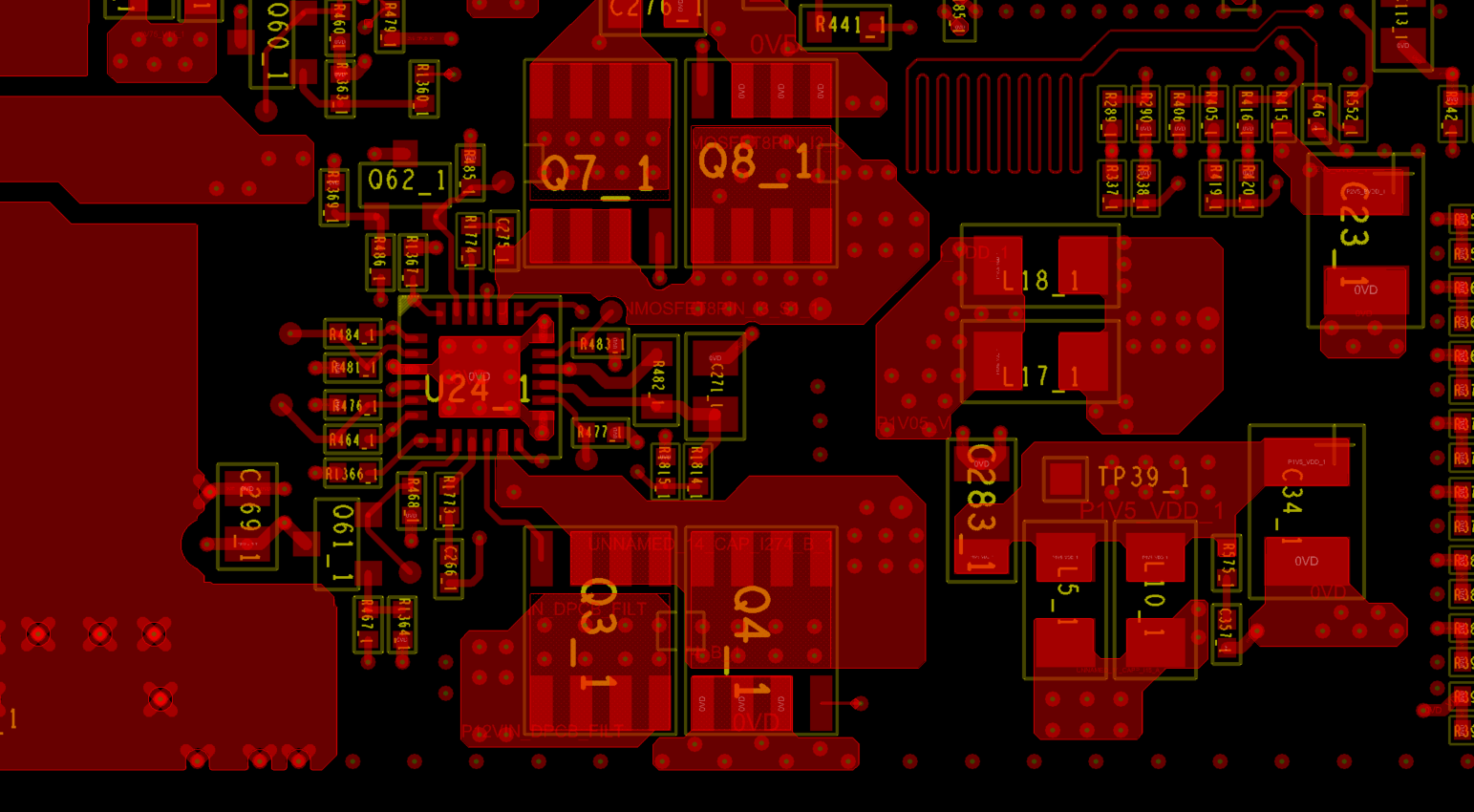
I'm wondering if there is a weakness in our layout, and a change in device characteristic tips them over the edge?

Any suggestions would be greatly appreciated.

  • Hi, I see the MSL is level2, if the moisture is too high with long time, possibly will cause some problem.

    Below suggestions for reference.

    1, if you find issue board, just heat the 59124 IC only, check whether it can work normally after baking.

    2, also you can find two boards, one normal board and one issue board, just swap the IC to check the issue follow IC or follow the board.

    if you suspect something is related to layout, please upload your files to review. but suggest you do above two items first to confirm what cause this happen.

    Yuchang

  • Thank you for your reply.

    I will try locally heating the device only next time I have opportunity.

    I have noticed 2 problems which may provide a clue;

    1. The PG line is showing short spikes at around the switching frequency 300kHz - during startup the spikes reach around 0.8V (2.5V pullup), once in regulation the spikes are about 0.2V

    2. I noticed that the layout has joined both PGND pins to the Pad underneath the device – which the datasheet specifically instructs not to.


    Could the PGND-Pad connection induce the spikes?

    Could the spikes on PG be related to the lack of power good signal?

  • Do you have waveforms share? generally if the loading is bigger during start up than normal working, the bigger ground noise will be generated, so you can see the noise is bigger during power up, suggest you check the PG line whether is too close to noise net, like DRV/BST/LL...switching noise,and PGND connect to the IC pad will increase the noise. but if the Vout and EN are all ok, PG should output even there is some noise. so first of all recommend to confirm what cause the problem happen, the board or the IC?

    Yuchang

  • Here are 2 plots showing (1) PG & Vout for a bad board and (2) PG & Vout for a good board

  • The noise is exactly a little big, but I still think that should not cause PG be kept pulled low, and I also saw another difference is Vout waveform, abnormal one has some drop and overshoot after getting to the normal operation, could you please share schematic and layout for review?

    Yuchang

  • Here is the relevant part of the schematic, and top and bottom layout (also included bottom layer flipped for readability).

    The next layers within the pcb (below top, & above bottom) are solid ground.

    8836.schematic.pdf

    Top Layer:

    Bottom Layer:

    Bottom Layer (flipped)

  • No critical points found to cause this issue happen from your pictures, more questions need you confirm

    1, For the big noise at PG signal, When testing PG signal which ground test point you used?

    2, Have you confirmed the issue follow IC or follow the motherboard?

    3, There are two PG outputs, only 1.05V power rail PG output abnormally or both? if only 1.05V rail happen the issue, did you try to disable the good channel(1.5V rail) to check whether the issue still happen?

    4, Also you can compare the impendence of IC each pin to ground, good board & bad board. if some pin has big difference impendence, maybe something is wrong with the pin.

    Yuchang

  • 1, For the big noise at PG signal, When testing PG signal which ground test point you used?

    > I've tried using a ground point near the device as well as further away - near the device makes the noise a little worse, but otherwise looks the same.

    2, Have you confirmed the issue follow IC or follow the motherboard?

    > not yet - this is difficult to do as I cannot remove the device without heating it, and I know that if I heat the board to 60 deg for a period of time it will cure the fault. I am trying to find a way to re-introduce the fault after it has been baked.

    3, There are two PG outputs, only 1.05V power rail PG output abnormally or both? if only 1.05V rail happen the issue, did you try to disable the good channel(1.5V rail) to check whether the issue still happen?

    > On most boards it is the 1v5 rail that is abnormal. On one board it is both rails. On the board I am currently looking at it is the 1v05 rail that is abnormal - if I disable the good rail (1v5) it makes no difference. Although I did notice that when turning the good rail back on, it induces those large spikes on the PG line.

    4, Also you can compare the impendence of IC each pin to ground, good board & bad board. if some pin has big difference impendence, maybe something is wrong with the pin.

    > I have checked all pins, and they are all within the range seen on other good boards.

    Harvey.

  • 1, For the big noise at PG signal, When testing PG signal which ground test point you used?

    > I've tried using a ground point near the device as well as further away - near the device makes the noise a little worse, but otherwise looks the same.

    >>> I think your board should be at least 6 layer, adjacent top and bottom are Ground and other 2 layer for signal and power distribution, right? If so, the layer stack looks ok, so confused why exist big noise happen if you already select a AGND test point.

    Below two suggestions for layout improve.

    1> The purpose with L17_1/2 is to filter high-frequency noise for Vout, but some vias are under inductor and close to switching node, may cause Vout coupled more switching noise.

    2> Recommend to add more high-frequency filter caps at drain of MOSFET, such as 0.1uf, 10nf..which will help to absorb High mosfet switching noise.

    2, Have you confirmed the issue follow IC or follow the motherboard?

    > not yet - this is difficult to do as I cannot remove the device without heating it, and I know that if I heat the board to 60 deg for a period of time it will cure the fault. I am trying to find a way to re-introduce the fault after it has been baked.

    >>>Understand you, After swapping IC, maybe both good board and issue board will work normally, but still need you to confirm it, and meanwhile please check whether IC thermal pad soldering is well or not?

    As you said after high temperature the issue gone, so what I want to know is whether the issue will be worse at lower temperature. you also can try to check if the good board also happen the issue at low temperature.

    3, There are two PG outputs, only 1.05V power rail PG output abnormally or both? if only 1.05V rail happen the issue, did you try to disable the good channel(1.5V rail) to check whether the issue still happen?

    > On most boards it is the 1v5 rail that is abnormal. On one board it is both rails. On the board I am currently looking at it is the 1v05 rail that is abnormal - if I disable the good rail (1v5) it makes no difference. Although I did notice that when turning the good rail back on, it induces those large spikes on the PG line.

    >>>I just want to check if disable one channel to lower the noise, then the issue may go away, but looks it is no use..

    Finally if you find the issue is exactly related to IC, you can contact local FAE or sales to submit FA request to do more analysis.

    Yuchang

  • Hi, Any update, or you have already contact local FAE support for further? I will close this thread first, you can reopen it if you need more help.

    Yuchang

  • Hi,

    Any new found from your side?

    If no, I recommend to focus on ABA test (swapping good board IC with bad board IC)to confirm whether the issue will follow IC or not, even though maybe the issue will be gone after heating, don't care, just do it first.

    or make the board in low temperature to see whether the issue will be changed more easier to happen..

    It is important to confirm the issue follows IC or the board, please focus on this first.

    Yuchang

  • Hi,

    the devices have been x-rayed, confirming the thermal pad is sound.

    I have applied freezer spray to a working board (regulator and vicinity) and it does not stop it from working.

    I have applied freezer spray to a non-working board and it does not fix it.

    Your ABA test proposal is the right thing to do, but it is impossible to do this without fixing the problem in the process;

    We did initially change the regulator for a new device, which did fix the problem, but then we noticed that simply heating the board to 60C without changing any components fixes the problem - so there is no way to determine whether the problem follows the device or the board.

    I have tried to re-introduce the problem by increasing humidity around the regulator, but so far that has not caused the problem to reappear.

    What I plan to do is gently heat the associated components (FETs etc) while cooling the regulator itself, and then heat the regulator itself while cooling the associated components - hopefully this will show whether or not it is actually the TPS59124.

    However, I am not going to do this until I am sure there is no more value in keeping the bad board to investigate, as this is my last non-working example, and once it is has been heated (and hence fixed) I will have no more examples with which to investigate the root cause.

    Thanks,

    Harvey.

  • Agree with your plan, let's exclude components step by step.

    "What I plan to do is gently heat the associated components (FETs etc) while cooling the regulator itself, and then heat the regulator itself while cooling the associated components - hopefully this will show whether or not it is actually the TPS59124."

    Yuchang

  • ok, I now have some more broken boards to investigate. Here is the result;

    I heated the regulator and FETs to around 80 degrees for 15 minutes - no effect.

    I heated just the 330uF output cap to around 80 degrees, and within 2 minutes it came good, so definitely the cap that is causing the issue.

    The ESR of that cap is critical for regulator operation, so maybe the ESR has changed while the board was in storage?

    So how do I prevent this issue from happening? are there any other capacitors families recommended for use with this regulator?

    Thanks,

    Harvey.

  • Sounds good if it can be fixed related to output caps, which kind of caps did you use, E-cap, or OSCON cap, As I know, pos-cap is popularly used for most customer.

    Below is some suggestions:

    1, Change new caps to try whether the issue gone

    2, follow formula 4 in datasheet to select proper caps, generally Panasonic pos-cap with ESR around 20mohm is OK.

    Yuchang

  • Hi, yes I am using POSCAP (6TPE330MAP) 25mohm ESR.

    I could change to another manufacturer, but I wont know for sure its fixed without waiting another 12 months!!

    But at least that would force the use of fresh stock which may help.

    Harvey.

  • So if it is caused by the output caps characteristic change, suggest you ask the cap Vendor for the root cause, check ESR change, capacity value change....or others and get the reason.

    Yuchang

  • Hi, If no more discussion for this question, it will be closed.

    Yuchang.

  • Hi, yes I think we can close this one - its definitely the caps going bad that have caused this issue (possibly due to the caps being MSL 3 and populating with old stock - fresh stock should solve it).

    However, before you close it, can you advise on the limits of ESR for the output cap for that regulator?

    I have performed a crude in-circuit measurement which shows that the bad cap has about 20% reduction in capacitance compared to a good cap (no issue with that), and about 75% increase in ESR.

    It seems that the increase in ESR is what kills it.

    I have demonstrated this to myself by replacing the output cap with a very low ESR cap (ceramic) and this works fine, and also with a high ESR cap (electrolytic) and the regulator will not work.

    I cannot see anything in the datasheet that indicates a maximum ESR, just a value to aim for.

    Thanks,

    Harvey.

  • Harvey, For ESR spec. just follow formula 4 and formula 9 in datasheet to determine it. And follow your description if the caps ESR added 75%, it is only around 25*1.75=44mohm, actually I don't think this will make the converter work abnormally if it can meet formula 4 and 9, maybe except ESR/Value change, some other AC characteristic also has been changed as well, but I am not sure. anyway if the problem fixed, that will be OK.

    Also suggest you follow formula 4 and 9 to double check whether the new caps you selected are OK or not.

    Yuchang

  • Formula 4 specifies the minimum ESR.

    Formula 9 indicates that if I have a low load, I need a high ESR.

    So yes, I agree, according to the data sheet 44mohm should not be a problem.

    Hmm, must be a peculiarity of my implementation.

    Thanks for your help.

    Harvey.