This thread has been locked.

If you have a related question, please click the "Ask a related question" button in the top right corner. The newly created question will be automatically linked to this question.

BQ79606A-Q1: UART communication with MSP432 mC (Read register)

Part Number: BQ79606A-Q1

Hi,

I am trying to interface BQ79606EVM with MSP432 mC. I was able to wake up the BQ79606EVM using the WAKEUP PIN by sending signal on the GPIO pin of MSP432.

However, I am unable to read a register from BQ79606. In the mC, I am using 12Mhz and have set UART with Baud rate of 1Mhz. I have been sending the single device read code to fetch the information.

Kindly advise.

Here are the code snippets I have used-

a) MSP432  BRS settings parameter for clk source 12MHz and Baud rate 1 Mhz-

const eUSCI_UART_ConfigV1 uartConfig =

{

        EUSCI_A_UART_CLOCKSOURCE_SMCLK,          // SMCLK Clock Source

        12,                                     // BRDIV = 78

        0,                                       // UCxBRF = 2

        0,                                       // UCxBRS = 0

        EUSCI_A_UART_NO_PARITY,                  // No Parity

        EUSCI_A_UART_LSB_FIRST,                  // LSB First

        EUSCI_A_UART_ONE_STOP_BIT,               // One stop bit

        EUSCI_A_UART_MODE,                       // UART mode

        EUSCI_A_UART_LOW_FREQUENCY_BAUDRATE_GENERATION,  // Oversampling

        EUSCI_A_UART_8_BIT_LEN                  // 8 bit data length

};

b) Read VCELLH register - Directly sending the hex values through UART to BQ79606

  unsigned char comm_frame[7] = {0x80,0x00,0x02,0x15,0x01,0xCB,0x49};

//loop to send all the 7 hex values

while(i_loop < 7)

        {

            while( !(UCA2IFG & UCTXIFG) );

            EUSCI_A_CMSIS(EUSCI_A2_BASE)->TXBUF = comm_frame[i_loop];

            i_loop++;

        }

//delay code comes here

//another loop written to receive values in a buffer

while( !(UCRXIFG) );

            *resp_ptr  = EUSCI_A_CMSIS(EUSCI_A2_BASE)->RXBUF;

Regards,

Navin

  • Hi Navin, 

    You need to first configure the ADC and then run it before you can read the cell values. Please review the software design reference for this device. In this document you'll find the initialization steps, auto-address and how to start ADC conversions.: http://www.ti.com/lit/an/slva970e/slva970e.pdf

    I also recommend that you start with the device GUI to get familiar with the commands that you need to send and you can also capture the communication on RX/TX in the oscilloscope to compare with the signals generated by your MCU and make sure the timing is correct. Here is the GUI manual: http://www.ti.com/lit/ug/sluubq2c/sluubq2c.pdf

    Best regards,

    Leslie

  • Hi Leslie,

    Thanks for your reply. I am aware of the GUI steps. In the GUI, even without starting ADC conversion, I could go to the registers tab & read values in registers, which is what I was attempting.


    However, I will now follow the list of steps & then try to read the cell values.

    At the same time, could you please enlighten me on the timing aspects, what are the common items that needs to be taken care of. I assume you are referring to the baud rate here.

    I understand that on wake up, the device has 1Mbps baud rate. Is that right?

    Regards,
    Navin

  • Hi Leslie,

    Also, before I start reading cell values. What is the easiest (register) value to get an output on the TX pin of bq79606 (output from BMS IC) by passing values from mC.

    I ask this because I want to check UART Reception from bq79606, before adding further functionalities which require more involved timing.

    Regards,

    Navin

  • Hi Navin,

    Yes, the device is configured to 1Mbps by default. A couple of things to consider are the time needed for the device to go to active mode after a wake pulse is received (tsu(wake) parameter in the datsheet ~7ms). You'll need to wait this long before communicating to the device. To make sure the frame you send out to RX has the correct structure the easiest way is to write/read a register from the GUI, capture the signal, and then do the same with your MCU code and compare the signals. This way you can compare byte by byte and also check your CRC is correct. For your initial debugging you can use registers 0xC2-0xC5 to write and read the values you want. Once you get your communication working just leave these registers to their default value.

    Best regards,

    Leslie 

  • Hi Leslie,

    Thanks a lot for this wonderful suggestion. It definitely shortened my efforts significantly. I am able to receive signal from TX of bq79606, which I was not able to do before.

    However, I was trying your approach to read the codes from the GUI on my MCU to compare the signals. I also tried to read codes send by TX of bq79606.

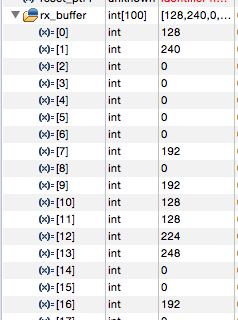
    In both cases, it appeared to me that I am receiving some constant stray codes (not exactly stray because the values happened to be 80, C0, E0, etc.) - screenshot below of values captured from TX of GUI in a buffer. My question is does the FTDI cable (or GUI) and TX of bq79606 constantly send signals. If not what could be the reason for me to receive them in MCU.

    The reason I ask FTDI cable itself is because, even when I remove the FTDI cable from the USB slot, I am able to receive signals. This stops as soon as I disconnect my RX in MCU.

    Regards,

    Navin

  • Hi Navin,

    That does not seem right. 

    That's not what I meant with my suggestion. 

    What I suggested is to connect the BQ79606A-Q1 to the PC through the FDTI cable and to connect an oscilloscope probe (or logic analyzer) on the RX and TX lines from the BQ79606A-Q1. You could also monitor the WAKEUP pin. Then send a write command from the GUI and capture the frame on the oscillsocope.

    Then, using your MCU instead of the GUI, send the same command from your MCU and capture the same signals on the BQ79606A-Q1.

    That way you can compare the frames with both solutions and see if the frame sent from your MCU is correct. 

    Best regards,

    Leslie

  • Hi Navin,

    I'm going to close this thread since we haven't heard back from you. If you still need help please create a new thread. 

    Regards,

    Leslie

  • Hi Leslie,

    Sorry for the delayed response. I think I did get you right except for one minor difference. I do not own an oscilloscope/logic analyser.

    I used the UART module of the mC to do the work of logic analyser (basically, read the hex values) sent from GUI.

    I was able to figure out the right command frames and it is working as expected. Your response solved my issue. Thanks a ton!

    Regards,

    Navin

  • Hi Navin,

    I'm glad your code is working now! If we helped you resolved your issue please click the "This resolved my issue" button below so other users know this is a verified answer when they run into a similar issue.

    Best regards,

    Leslie