This thread has been locked.

If you have a related question, please click the "Ask a related question" button in the top right corner. The newly created question will be automatically linked to this question.

TPS62740: VSELn drive levels.

Part Number: TPS62740

Hello,

  We plan to control this part from a 1.8V logic level micro-controller while Vin to TPS62740 is 3.2V. 

 In this case, is it required to drive VSELn high level to 3.2V to avoid increases to quiescent current?

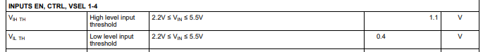
This consideration aside, VIH TH,max as specified is  1.1V. 

Thanks in advance for your help!

Faizal.

  • Hi Faizal,

    For a buck converter, Vout should be always less than Vin. We do not have 100% efficiency. So please set Vout lower than 3.2V Vin (by selecting corresponding VSELn combination). 

    The parameters VIH and VIL are related to logic high and logic low levels of the pins EN, CTRL, VSELn. It has no relation with input voltage values. Which means, if you apply 1.1V the pin will detect a logic high and when it is 0.4V it will detect logic low.

    If this explains your question please hit resolve button. In case you need further help, feel free to contact us.

    Regards,

    Febin

  • Thank you for the response.

    The concern was about the potential for shoot through current (and therefore more quiescent current) when logic level control signals such as VSELn, EN or CTRL are driven high to a level that is higher than their Vih threshold but lower than the input voltage VIN to TPS62740. 

    The data sheet says that these lines must be 'terminated'. 

     What is the impact to quiescent current while the control lines are terminated to 1.8V (which is greater than Vih threshold) ?

    Best Regards,

    Faizal.

  • Hi Faizal,

    I understand that here Vin is 3.2V. So, obviously Vout should be less than this value. 

    As I mentioned previously, The parameters VIH and VIL are related to logic high and logic low levels of the pins EN, CTRL, VSELn. It has no relation with input voltage values.

    For EN, CTRL, VSELn, it is safe to operate until 3.2+0.3V in this case. But again VSELn needs to be set to less than 3.2V.

    Regarding the CTRL pin: 1.8V , it will be a logic high (because greater than VIH 1.1V) and the output LOAD is enabled. When CTRL pin is set to high, the Quiescent current of the DCS control block is increased to typ. 12.5µA.

    Quiescent current is when the device is not switching. (EN is logic high). There is no impact of VIH 'values' (1.1V and above for logic high; 0.4 and below for logic low) on Iq. It is dependent on the logic conditions.

    Please explain what you mean by shoot through current? Do you mean the inrush current? It is again not dependent on the values but the logic conditions- high or low. The threshold given in the datasheet is the min/max values to detect a high or low logic levels solely for these pins. Inrush current also depends on the output load and supply voltage ramp up. 

    Please refer to Electrical Characteristics (Page No.5) to find out the Operating Quiescent current according to your pin conditions.

    Hope I explained your question. Please let me know if you have further questions. 

    Regards,

    Febin

  • Thanks Febin.

    It is clear that the logic level control signal voltages (VSEL, CTRL etc) must not exceed Vin+0.3V. 

    It is also clear that CTRL=enabled implies more quiescent current.

    It seems that you are indicating that there is not a need to level shift each control signal (for VSEL)  externally to (Vin = 3.2V).

    By shoot-through current I meant CMOS shoot-through when any P-channel and N-channel devices, at the logic level control inputs, are partially on at the same time. 

    It looks like level shifting each control signal (for VSEL)  to Vin=3.2V is not a requirement to use the part.

    With best regards,

    Faizal.

  • Hi Faizal,

    Correct. It is not required to have 3.2V at VSEL pins to detect a high. 1.1V should be enough.

    Regards,

    Febin