This thread has been locked.

If you have a related question, please click the "Ask a related question" button in the top right corner. The newly created question will be automatically linked to this question.

TPS65130: Positive Rail doesn't give the right voltage

Part Number: TPS65130

Dear reader.

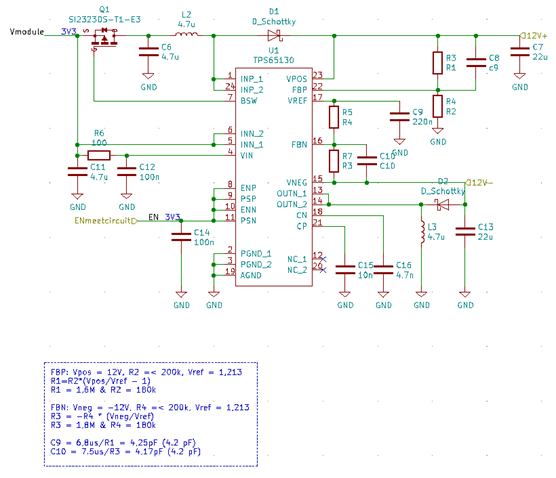
I made my own PCB with the following schematic:

C10(value C10) and C8(value C9) are not solderd

With my first and only solderd PCB i did a test.

Test TPS65130 1st PCB solderd

Cheap multimeter borrowed from school (Peaktech 3340 DMM)

Vin = 3.3V @ 129 mA

Vout positive = 8.10V

Vout negative = -12.16V

ENP = PSP = ENN = PSN = 3.3V

FBP = 0.826 V

FBN = -0.120 V

Vref = 1,227 V

Before positive diode = 3.27 V

The problem is that i made this circuit to convert 3.3V to +12V and -12V.
I only get +8V and -12V. My problem is why do i get the +8V and what do i need to change to get +12V?

  • Hi Jim,

    Thanks for your question. Let me contact the expert for this part. You can expect a response by 3/10/20.

    Best,

    Grant

  • Dear Grant/expert

    This morning i solderd a new PCB, this one worked right away. an open voltage test gave me:

    Vin = 3.3V @ 2.27 mA

    Vout positive = 12.00V

    Vout negative = -12.00V

    ENP = PSP = ENN = PSN = 3.3V

    FBP = 1.302 V

    FBN = -0.027 V

    Vref = 1,223 V

    After 3/4 hours of testing the inverting converter went off.

    I have tried to put the enable pins on low and back on high, turning off and on the power supply but nothing did work.

    How can i fix the inverting converter or how can i find the problem?

  • Hi Jim,

    Why are C9 and C10 capacitors not soldered? I would suggest to:

    - solder C9 and C10 with the calculated values.

    - install an approx. 51K resistor between C10 and 12V- net. This resistor limits feed forward bandwidth and reduces noise coupling into FBN pin.

    - connect PSP and PSN pins 9 and 11 to GND permanently.

    I also still suspect some assembly issue if the board worked for 3/4 of an hours and than stopped. So please double check all soldering/PCB connections. I hope these suggestions and helpful and resolve any issues with your board.

    Kind Regards,

    Liaqat

  • Dear Liaqat,

    Soldered C9 + C10 and the 51k resistor, it wasn't possible to put PSP and PSN to the GND.
    This didn't change anything.

    But i soldered 2 new PCB's and have been testing them both for 2 days now in total.

    They are both working according to my schematic without the C9 and C10 soldered.