A related question is a question created from another question. When the related question is created, it will be automatically linked to the original question.
If you have a related question, please click the "Ask a related question" button in the top right corner. The newly created question will be automatically linked to this question.
Sorry to hear that you are still having trouble. With regards to the previous image, HO should still not have a forward drop of 10V when you are conducting through the body diode to the SW. Do the scope shots that you've provided before match what you are seeing now, or has anything changed?
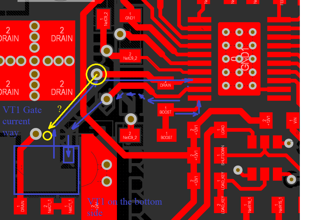
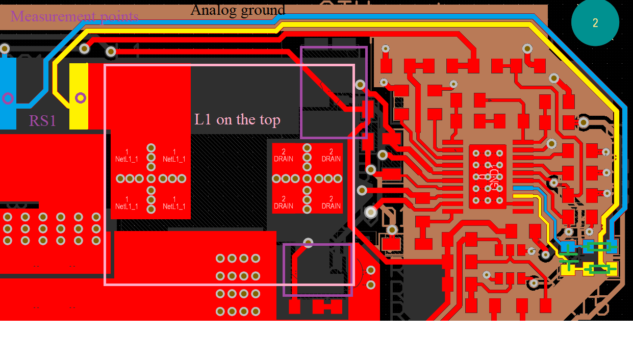
As for the path- i think you should not have the 12V1 trace cut through the trace to VT1. Since that is an input rail, you could take a longer path around the FET.
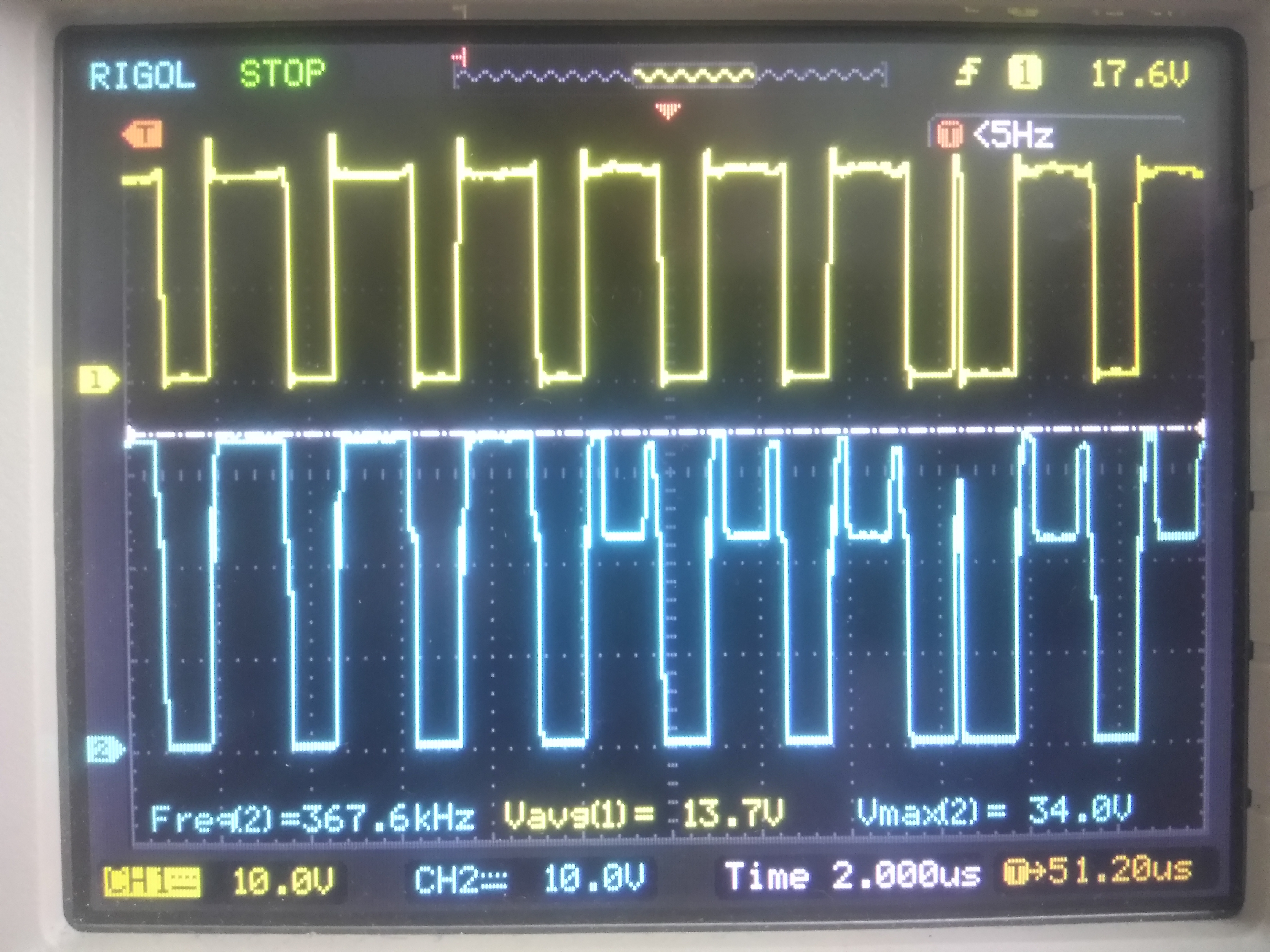
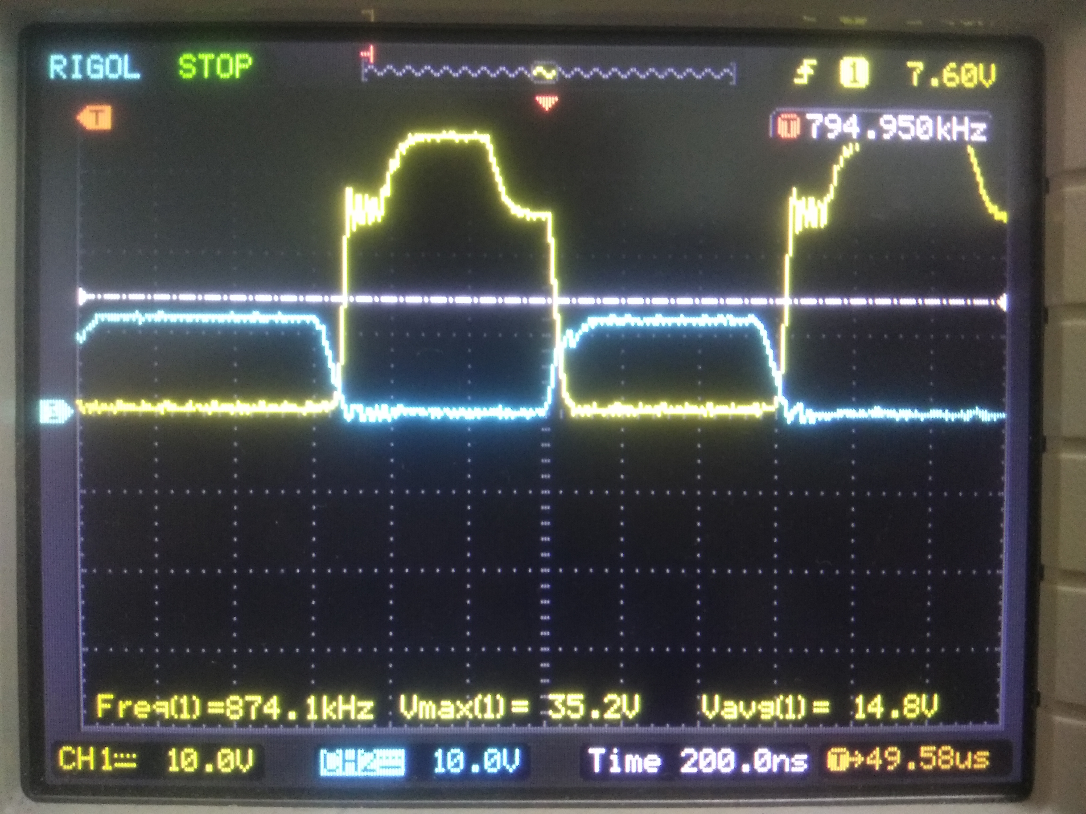
SW (top) and HO (bottom) signal respect to the groung are presented on this picture. At first HO signal is normal, but then gaps are appeared on the top of pulses. May be this behavor is related to power integrity? (DC-DC was under 3 Ohm load conditiion)
The cause of unstable operation was Hiccup-Mode Overload Protection. i changed capacitor on Res pin by 0 ohm resistor and DC-DC started under 3 ohms load, but then VT2 was failure. I choose 2 mOhms current sense resistor. Is it correct choise for this application? I changed VD2 to jumper and gaps on the tops of HO pulses were remove. What do I make wrong?
Thanks for clarifying. How did VT2 fail? By connecting RES to AGND, you have removed hiccup-mode protection and are now in cycle-by-cycle current limit.
To check if you are in current limit, can you show a scope shot of inductor current? If you are in current limit, you may need to decrease the size of of your current sense resistor to add margin.
For selecting current sense resistor, you need to make sure that the peak current value it can handle is equal to your peak inductor current +/- 30%. That should be a good starting point.
As for VD2, whether you have a jumper or not should not be an issue, since having an external VCC bias reduces thermal dissipation in the IC.
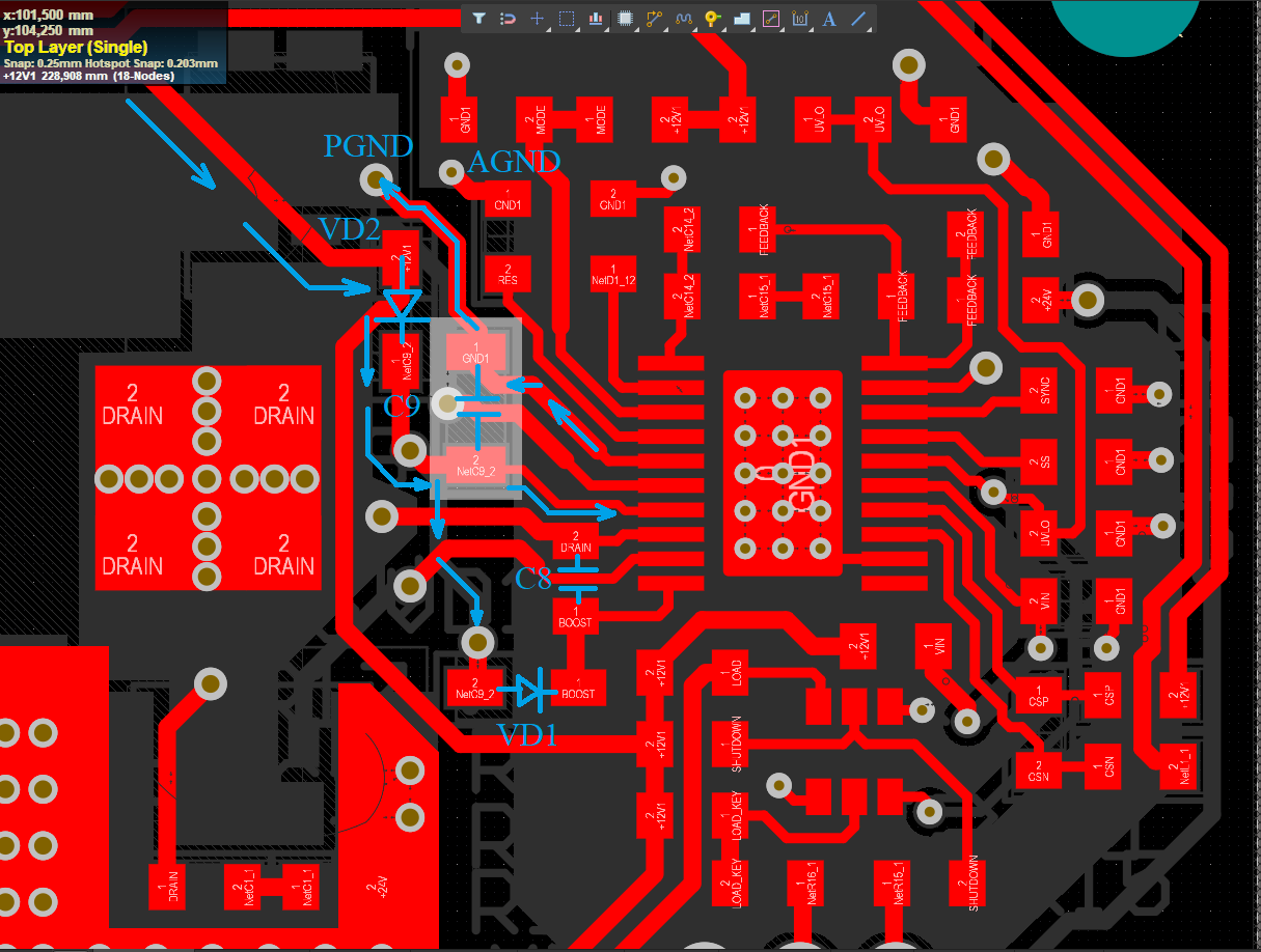
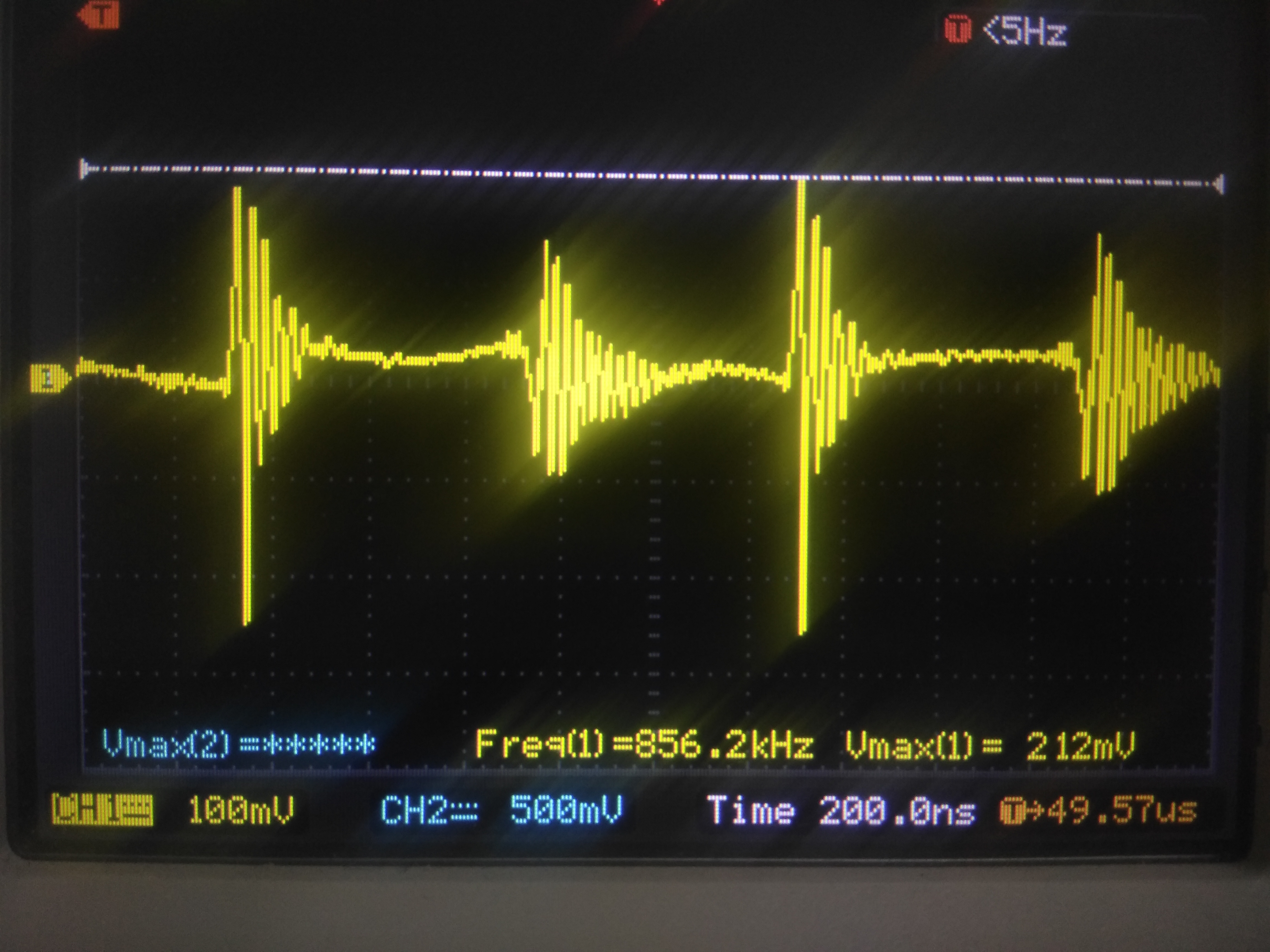
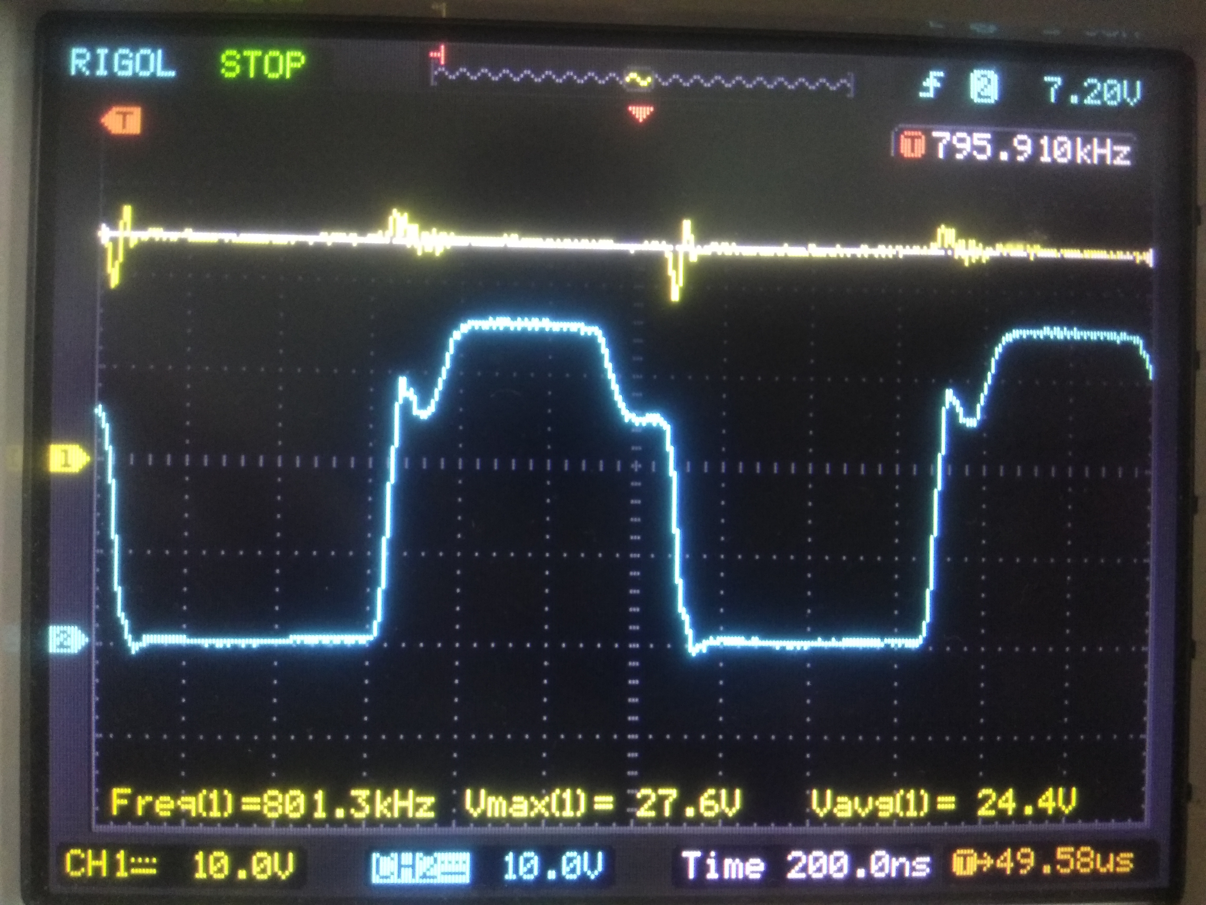
Hi, I have measured current signal on the current sense resistor before filter. It has strange form, but dc-dc works with off hiccup mode. Maybe it's related for EMC? (Load 4 Ohm) Are the current sense tracks not too long?)
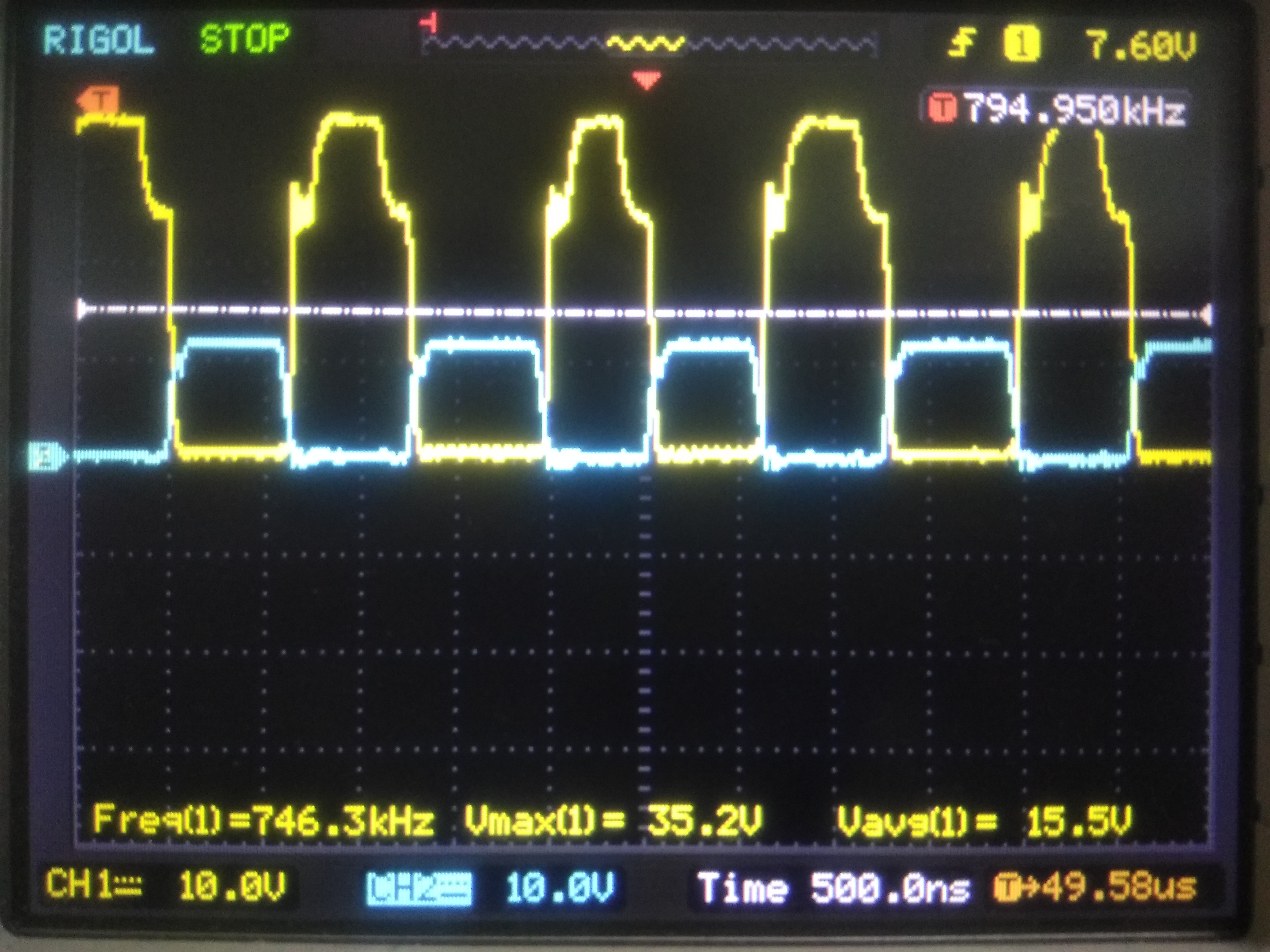
I made some scope shots. First shot is HO and LO when DC-DC under 3 ohm load. Hiccup mode is enable.
I have solded 11 kOhm frequency setup resistor and 75 kOhm slope compensation resistor.But output voltage had spikes when HO was closing. And I redesigned current sense filter, 100 ohm resistor was replaced by 1,2 kOhm.
I think transistors have opening together sometimes, and short circuit is happened. May be IRF7480 is too slow for 800 kHz applications? It has tur on delay - 21 ns, turn on time - 70 ns, turn off delay - 68 ns and turn off time - 58 ns. How can I connect Pspice model of Lm5122 to my altium library and simulate it? I can't find any files with *.ckt file format for LM5122.
I think the FET is fine, since your IRF7480 FET has a turn-on-time of 70ns and delay time of 21ns, which is fast enough.
Your current sense traces are too long, you will need to reorient your current sense traces to be shorter. In this case, I would recommend you to download the PSPICE model, and simulate your schematic to assess performance: http://www.ti.com/product/LM5122/toolssoftware
You can also download the TINA-TI model of the LM5122, and modify it as needed to assess that the schematic works well before you do another spin of the layout.
I have downloaded lm5122 SPICE models. I don't understand how to use it. What programm I need to use for simulation? I use Altium Designer for my designs, but I don't know how connect this models to my design. Archives aren't containe *.ckt or *.mdl files.
I have analyzed TI referecnce desingns (98% 135W Single Phase Boost Reference Design, 154W Synchronous Boost Converter Reference Design, 200W Synchronous Boost Audio Amplifier Reference Design). Transistors in this designs are greatly faster than IRF7480. For more current capability in this designs are used two transistors in parallel connection for more current capability.
Hi Richard, I have downloaded lm5122 SPICE models. I don't understand how to use it. What programm I need to use for simulation? I use Altium Designer for my designs, but I don't know how connect this models to my design. Archives aren't containe *.ckt or *.mdl files.
I have analyzed TI referecnce desingns (98% 135W Single Phase Boost Reference Design, 154W Synchronous Boost Converter Reference Design, 200W Synchronous Boost Audio Amplifier Reference Design). Transistors in this designs are greatly faster than IRF7480. For more current capability in this designs are used two transistors in parallel connection for more current capability.
Hello, I try to simulate my design but I have a trouble. I attach simulation project and orginal spice model of IRF7480 by Infeneon (irf7480mtrpbf.spi) and model IRF7480 by me (irf7480mtrpbf.cir https://e2e.ti.com/cfs-file/__key/communityserver-discussions-components-files/196/IRF7480.7z), I corrected original file but It wasn't sucsessfull. Can you help me to starting simulation?4617.LM5122.TSC
Apologies for the delay this week. When I run the converter with the TINA-TI settings: Analysis->Transient->"use initial conditions", the simulation will start up. I will take a more detailed look into this and give you a response by next week.
Hello, great thanks for your answer, Richard. Modeling results looks ok (https://e2e.ti.com/cfs-file/__key/communityserver-discussions-components-files/196/LM5122.7z) . How can I investigate conductive electromagnetic interference levels with TINA-TI? I want to try add input and output EMC filters to my design.
This will take me a bit of time to understand how to use the signal analyzer tool, so I will get back to you next week. Is there a specific reason you do not want to use the average model for the AC analysis as mentioned in the previous post?